OPERATION AND PARTS MANUAL MODEL GDP-5H High Cycle Generator (HONDA GASOLINE ENGINE) Revision #2 (10/05/05) THIS MANUAL MUST ACCOMPANY THE EQUIPMENT AT ALL TIMES.
PAGE 2 — GDP-5H A.C. GENERATOR— PARTS & OPERATION MANUAL — REV.
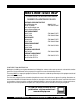
HERE'S HOW TO GET HELP PLEASE HAVE THE MODEL AND SERIAL NUMBER ON-HAND WHEN CALLING MULTIQUIP CORPORATE OFFICE 18910 Wilmington Ave. Carson, CA 90746 Email: mq@multiquip.com Internet: www.multiquip.com PARTS DEPARTMENT 800-427-1244 310-537-3700 MAYCO PARTS 800-306-2926 310-537-3700 SERVICE DEPARTMENT 800-421-1244 310-537-3700 TECHNICAL ASSISTANCE 800-478-1244 WARRANTY DEPARTMENT 800-421-1244, EXT. 279 310-537-3700, EXT.
TABLE OF CONTENTS Multiquip GDP-5H — AC Portable Generator Here's How To Get Help ............................................ 3 Table Of Contents ..................................................... 4 Parts Ordering Procedures ....................................... 5 Safety Message Alert Symbols .............................. 6-7 Rules for Safe Operation ..................................... 8-10 Operation and Safet Decals .................................... 11 Specifications (Generator) ...............
PARTS ORDERING PROCEDURES When ordering parts, please supply the following information: ❒ ❒ ❒ ❒ ❒ ❒ ❒ Dealer account number Dealer name and address Shipping address (if different than billing address) Return fax number Applicable model number Quantity, part number and description of each part Specify preferred method of shipment: ✓ FedEx or UPS Ground ✓ FedEx or UPS Second Day or Third Day Note: Unless otherwise indicated by customer, all orders are treated as “Standard Orders”, and will ✓ FedEx or UPS Nex
GDP-5H — SAFETY MESSAGE ALERT SYMBOLS FOR YOUR SAFETY AND THE SAFETY OF OTHERS! HAZARD SYMBOLS Safety precautions should be followed at all times when operating this equipment. Failure to read and understand the Safety Messages and Operating Instructions could result in injury to yourself and others.
GDP-5H — SAFETY MESSAGE ALERT SYMBOLS CAUTION Rotating Parts Hazards NEVER operate equipment with covers, or guards removed. Keep fingers, hands, hair and clothing away from all moving parts to prevent injury. CAUTION CAUTION Equipment Damage Hazards Other important messages are provided throughout this manual to help prevent damage to your portable generator, other property, or the surrounding environment.
GDP-5H — RULES FOR SAFE OPERATION DANGER Read this manual! Failure to follow instructions in this manual may lead to serious injury or even death! This equipment is to be operated by trained and qualified personnel only! This equipment is for industrial use only. The following safety guidelines should always be used when operating the GDP-5H Portable Generator: GENERAL SAFETY ■ DO NOT operate or service this equipment before reading this entire manual.
GDP-5H — RULES FOR SAFE OPERATION ■ ALWAYS be sure the operator is familiar with proper safety precautions and operation techniques before using generator. ■ NEVER leave the generator unattended, turn off engine when unattended. ■ Unauthorized equipment modifications will void all warranties. ■ ALWAYS ensure generator is on level ground before use. ■ DO NOT place hands or fingers inside generator engine compartment when engine is running.
GDP-5H — RULES FOR SAFE OPERATION DANGER -ELECTROCUTION HAZARDS During operation of this generation, there exists the possibility of electrocution, electrical shock or burn, which can cause severe bodily harm or even DEATH! Emergencies ■ ALWAYS know the location of the nearest fire extinguisher. ■ ALWAYS know the location of the nearest first aid kit. To avoid these hazards: NEVER use damaged or worn cables when connecting equipment to the generator.
GDP-5H — OPERATION AND SAFETY DECALS Machine Safety Decals The GDP-5H portable generator is equipped with a number of safety decals (Figure 1). These decals are provided for operator safety and maintenance information. The illustration below shows these decals as they appear on the machine. Should any of these decals become unreadable, replacements can be obtained from your dealer. Figure 1. Operation and Safety Decals GDP-5H A.C. GENERATOR — PARTS & OPERATION MANUAL — REV.
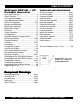
GDP-5H — SPECIFICATIONS (GENERATOR) Table 1. Specifications (Generator) Model Type Excitation GDP-5H Brushless Revolving Field Type Solid State, Statically Excited System AC Generator Speed Cooling System Fuel Capacity 60 Cycle AC Power Source 5 gallons (19 liters) 3.6 kW Stanby Output 4.0 kW Rated Voltage 120/240 V Rated Current 30 amps (120V) Rated Current 15 amps (240V) Frequency Power Factor Single Phase (4 wire) 60 Hz 1 Continuous Output 5 kVA Rated Voltage 230 V Rated Current 12.
GDP-5H — SPECIFICATIONS (ENGINE) Table 2. Specifications (Engine) Engine Model HONDA GX340K1EDN2 Type Air-cooled 4 stroke, Single Cylinder, OHV, Horizontal Shaft Gasoline Engine Bore X Stroke 2.90 in. X 2.30 in. (73 mm x 58 mm.) Displacement 23.70 cu-in (389 cm3) Max Output 11.0 H.P./3600 R.P.M. Fuel Lube Oil Capacity 1.16 quar ts (1.
GDP-5H — DIMENSIONS Figure 2. Dimensions PAGE 14 — GDP-5H A.C. GENERATOR— PARTS & OPERATION MANUAL — REV.
GDP-5H — GENERAL INFORMATION WARNING Before connecting this generator to any building’s electrical system, a licensed electrician must install an isolation (transfer) switch. Serious injury or death may result without this transfer switch. GDP-5H FAMILIARIZATION Generator The Multiquip Model GDP-5H generator has been designed as a portable dual purpose power source for 60 Hz (single phase) lighting facilities, power tools, submersible pumps and other industrial and construction machinery.
GDP-5H — LOAD APPLICATION Single Phase Load — 60 Hz Always be sure to check the nameplate on the generator and equipment to insure the wattage, amperage and frequency requirements are satisfactorily supplied by the generator for operating the equipment. Generally, the wattage listed on the nameplate of the equipment is its rated output.
GDP-5H — LOAD APPLICATION/EARTH LEAKAGE BREAKER Three Phase Load — 180 Hz 180 Hz, three phase, 230V, motor-in-head vibrators can be operated with this generator. When operating more than one concrete vibrator, the ON/OFF switch of each concrete vibrators shall be turned on one at a time. If they are switched on simultaneously, the circuit breaker may trip or the engine may be overloaded.
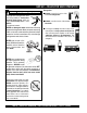
GDP-5H — CONTROLS AND INDICATORS Figure 4A. Generator Components 1. 230V Output Receptacles– These three NEMA 7410 twist-lock receptacles will provide 230V, 12.5 amps, 180 Hz. 2. 180 Hz Earth Leakage Circuit Breaker – This 3-pole earth leakage circuit breaker allows the circuit to be broken when the load side shorts or there is an over-current condition. In addition, during operation of the generator it can detect when there is defective insulation on the load side and breaks the circuit in response.
GDP-5H — CONTROLS AND INDICATORS Figure 4B. Generator Components 12. Full Power Switch – The generator is provided with a full power switch. Figures 4C and 4D show simplified wiring diagrams of the dual voltage system.
GDP-5H — CONTROLS AND INDICATORS Figure 4E. Generator Components 13. Fuel Cock Lever – Turn this lever downward to start (down)the flow of fuel into the carburetor. Turn upward to stop (up) the flow of fuel. 19. Engine Oil Drain Plug – Remove this drain plug when draining of the oil from the engine crankcase is required. Fill with recommeded type oil as listed in Table 6. 14. Spark Plug – Provides spark to the ignition system. Set spark plug gap to 0.6 - 0.7 mm (0.028 - 0.
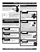
GDP-5H — GENERATOR REFUELING DANGER Adding fuel to the tank should be done only when the engine is stopped and has had an opportunity to cool down. In the event of a fuel spill, DO NOT attempt to start the engine until the fuel residue has been completely wiped up, and the area surrounding the engine is dry. If generator is placed in a truck bed with a plastic liner, REMOVE generator from truck bed and place on ground (Figure 5) to refuel.
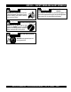
GDP-5H — INSTALLATION Outdoor Installation Indoor Installation Install the generator/welder in a area that is free of debris, bystanders, and overhead obstructions. Make sure the generator is on secure level ground so that it cannot slide or shift around. Also install the generator in a manner so that the exhaust will not be discharged in the direction of nearby homes. Exhaust gases from gasoline engines are extremely poisonous.
GDP-5H — INSTALLATION Connecting the Ground The nut and ground terminal on the generator should always be used to connect the generator to a suitable ground. The ground cable should be #8 size wire minimum. At the generator, connect the terminal of the ground cable between the lock washer and the nut (Figure 6) and tighten the nut fully. Connect the other end of the ground cable to a suitable earth ground (ground rod).
GDP-5H — PRE-INSPECTION General Inspection Prior to Operation Extension Cable Ground Power Tools When electric power is to be provided to various tools or loads at some distance from the generator, extension cords are normally used. Cables should be sized to allow for distance in length and amperage so that the voltage drop between the generator and point of use (load) is held to a minimum. Use the cable selection chart (Tables 4 and 5) as a guide for selecting proper cable size.
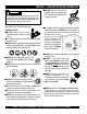
GDP-5H — PRE-INSPECTION (ENGINE) CAUTION NEVER operate the generator in a confined area or enclosed area structure that does not provide ample free flow of air. Figure 9. Engine Oil Dipstick (Oil Level) ALWAYS wear approved eye and hearing protection before operating the generator. Before Starting 1. Read safety instructions at the beginning of manual. 2. Clean the generator, removing dirt and dust, particularly the engine cooling air inlet, carburetor and air cleaner. 3.
GDP-5H — INITIAL START-UP (ENGINE) CAUTION 2. Place the choke lever (Figure 13) in the "CLOSED " position if starting a cold engine. DO NOT attempt to operate this generator until the Safety, General Information and Inspection sections of this manual have been read and thoroughly understood. This section is intended to assist the operator with the initial start-up of the portable generator. It is extremely important that this section be read carefully before attempting to use the generator in the field.
GDP-5H — INITIAL START-UP/GENERATOR OPERATION 6. If the engine has started, slowly return the choke lever (Figure 13 ) to the “OPEN” position. If the engine has not started repeat steps 1 through 5. 2. Place the full power switch (Figure 19) in the 120V position (up). 7. Before the generator is placed into operation, run the engine for 3-5 minutes. Check for abnormal smells, fuel leaks, and noises that would associate with lose components. 8.
GDP-5H — INITIAL START-UP/GENERATOR OPERATION 5. Read the voltmeter on the front panel of the generator (Figure 22) and verify that 240 VAC is present at the 240V twist-lock receptacle. Using an external voltmeter verify that 120V is present at the at the 120V twist-lock and GFCI duplex receptacles. 180 Hz Operation 1. Place the 180 Hz, 12.5 amp circuit breaker (Figure 23) in the ON position. Figure 23. 60 and 180 Hz Breakers (ON) 5.
GDP-5H — SHUTDOWN/ LONG TERM STORAGE Stopping the Engine 1. Place both the 60 and180 Hz circuit breakers (Figure 25) in the OFF position. 5. Place the engine fuel valve lever (Figure 28) to the "OFF" position.” Figure 28. Engine Fuel Valve Lever (OFF Position) Figure 25. 60 and 180 Hz Breakers (Off) 2. Place the idle control switch (Figure 26) in the OFF position. Figure 26. Idle Control Switch (Off) 3. Let the engine run at idle with no load for 2-3 minutes. 4.
GDP-5H — MAINTENANCE (ENGINE) Use Table 7 as a general maintenance guideline when servicing your engine. For more detail engine maintenance information, refer to the Honda engine owner's manual supplied with your engine. Table 7. Engine Maintenance Schedule DESCRIPTION (3) OPERATION BEFORE CHECK X FIRST EVERY MONTH 3 MONTHS OR OR 10 HRS. 25 HRS. EVERY 6 MONTHS OR 50 HRS. EVERY YEAR OR 100 HRS. EVERY 2 YEARS OR 200 HRS.
GDP-5H — MAINTENANCE (ENGINE) Maintenance Perform the scheduled maintenance procedures as defined by Table 6 and below: DAILY ■ Thoroughly remove dirt and oil from the engine and control area. Clean or replace the air cleaner elements as necessary. Check and retighten all fasteners as necessary. Check the gearbox for oil leaks. Repair or replace as needed. WEEKLY ■ Remove the fuel filter cap and clean the inside of the fuel tank. ■ Remove or clean the filter at the bottom of the tank.
GDP-5H — WIRING DIAGRAM (GENERATOR) S/N 5541049 AND BELOW Figure 32. Generator Wiring Diagram (S/N 5541049 and below) PAGE 32 — GDP-5H A.C. GENERATOR— PARTS & OPERATION MANUAL — REV.
GDP-5H — WIRING DIAGRAM (GENERATOR) S/N 5543731 AND ABOVE Figure 33. Generator Wiring Diagram (S/N 5543731 and above) GDP-5H A.C. GENERATOR — PARTS & OPERATION MANUAL — REV.
GDP-5H — TROUBLESHOOTING (ENGINE) Practically all breakdowns can be prevented by proper handling and maintenance inspections, but in the event of a breakdown, please take a remedial action following the diagnosis based on the Engine Troubleshooting (Table 8) and Generator Troubleshooting (Table 9) information shown below and on the proceeding pages. If the problem cannot be remedied, please leave the unit just as it is and consult our company's business office or service plant. TABLE 8.
GDP-5H — TROUBLESHOOTING (ENGINE) TABLE 8. ENGINE TROUBLESHOOTING (CONTINUED) SYMPTOM Insufficient power output "compression" and overheats Burns to much fuel Exhaust color is continiously "WHITE" Exhaust color is continiously "BLACK" POSSIBLE PROBLEM SOLUTION Malfunction in cooling fan? Check or replace cooling fan. Air in-take filter clogged? Clean or replace air in-take filter. Over accumulation of exhaust products? Clean and check valves. Check muffler, replace if necessary.
GDP-5H — TROUBLESHOOTING (GENERATOR) TABLE 9. GENERATOR TROUBLESHOOTING SYMPTOM Low voltage POSSIBLE PROBLEM SOLUTION Engine speed too low? Raise engine speed to rated RPM. AC voltmeter not working? Replace Ac voltmeter. Control box internal wiring malfunction? Check control box wiring. Defective ignition coil? Check red and green ignition wires. Replace ignition wires if necessary. Rotor winding malfunction? Check or replace rotor. Stator winding malfunction? Check or replace stator.
NOTE PAGE GDP-5H A.C. GENERATOR — PARTS & OPERATION MANUAL — REV.
GDP-5H — EXPLANATION OF CODE IN REMARKS COLUMN How to read the marks and remarks used in this parts book. NOTE The contents of this catalog are subject to change without notice. Items Found In the “Remarks” Column Serial Numbers-Where indicated, this indicates a serial number range (inclusive) where a particular part is used. Model Number-Where indicated, this shows that the corresponding part is utilized only with this specific model number or model number variant.
GDP-5H — SUGGESTED SPARE PARTS GDP-5H 1 TO 3 UNITS WITH HONDA GX340K1EDN2 ENGINE 1 to 3 Units Qty. P/N Description 1 ........A9924800014 ...........CAP FUEL TANK 1 ........A9924800004 ...........FILTER FUEL 1 ........3015419604 ..............SHOCK MOUNT 4 ........1665419004 ..............SHOCK MOUNT 1 ........9807955846 ..............SPARK PLUG 1 ........34150ZH7003 ...........ALERT UNIT, OIL 2 ........28462ZV7003 ...........ROPE, RECOIL 2 ........17211899000 ............
GDP-5H — NAMEPLATE AND DECALS. PAGE 40 — GDP-5H A.C. GENERATOR— PARTS & OPERATION MANUAL — REV.
GDP-5H — NAMEPLATE AND DECALS. NAME PLATE ASSY. NO. PART NO. 1 A4561000103 2 0600500047 3 1980680004 4 A4511200102 5 0600500045 6 7 0800628504 8 A9521200104 9 0820610404 10 A9511100004 11 7900636004 12 8700611804 13 8700611904 PART NAME QTY. REMARKS DECAL; MQ MULTIQUIP 5000 1 DECAL; CHOKE 1 DECAL; FUEL COCK .................................................. 1......... S-3704 DECAL; CONTROL PANEL ......................................... 1......... A41120010 DECAL; AIR CLEANER 1 NAMEPLATE ..................
GDP-5H — GENERATOR ASSY. GENERATOR ASSY. PAGE 42 — GDP-5H A.C. GENERATOR— PARTS & OPERATION MANUAL — REV.
GDP-5H — GENERATOR ASSY. GENERATOR ASSY. NO. PART NO. 7851000203 1 * 1-1 * 1-2 * 0601820037 1-3 * 0601822640 1-4 * 0071206304 1-5 * 7851017204 2 3 0801086104 4 030210250 5 A4135000003 6 7851315502 7 0017108020 8 A4154000002 9 A4138000003 10 011208025 11 1961324003 12 1961313003 13 0011305100 14 7851334204 15 7851316804 16 030208200 17 031108160 18 7851331103 19 0310300090 20 0017105012 21 0601820083 22 A4184000004 23 0027104020 23A 0038404000 24 0017108015 PART NAME QTY. REMARKS ROTOR ASSY. ...............
GDP-5H — CONTROL BOX ASSY. CONTROL BOX ASSY. PAGE 44 — GDP-5H A.C. GENERATOR— PARTS & OPERATION MANUAL — REV.
GDP-5H — CONTROL BOX ASSY. CONTROL BOX ASSY. NO. PART NO.
GDP-5H — MUFFLER ASSY. MUFFLER ASSY. PAGE 46 — GDP-5H A.C. GENERATOR— PARTS & OPERATION MANUAL — REV.
GDP-5H — MUFFLER ASSY. MUFFLER ASSY. NO PART NO PART NAME 1 2 3 4 5 6 7 8 9 10 11 12 13 14 15 7852310003 18320ZC2000 18325ZB4000 18329ZB4000 18355ZB4630 0602322060 0105050616 18333ZB4800 0602322061 7855469004 011008020 011008020 7905469004 011206020 0105050616 MUFFLER 1 PROTECTOR ......................... 1 ......... REPLACES P/N 0602302001 PROTECTOR ......................... 1 ......... REPLACES P/N 0602302002 SEAL ..................................... 2 .........
GDP-5H — PIPE FRAME ASSY. PIPE FRAME ASSY. PAGE 48 — GDP-5H A.C. GENERATOR— PARTS & OPERATION MANUAL — REV.
GDP-5H — PIPE FRAME ASSY. PIPE FRAME ASSY. NO. PART NO.
HONDA GX340K1EDN2 ENGINE — AIR CLEANER ASSY. AIR CLEANER ASSY. PAGE 50 — GDP-5H A.C. GENERATOR— PARTS & OPERATION MANUAL — REV.
HONDA GX340K1EDN2 ENGINE — AIR CLEANER ASSY. AIR CLEANER ASSY. NO. PART NO. 1 15721ZB4000 2 17211899000 3 17212ZB4003 4 17220ZB4003 5 17222ZC2000 6 17231899000 7 17235899000 8 17236899000 9 17252899000 10 17367413690 11 9405005000 12 9405006000 PART NAME TUBE BREATHER ELEMENT, AIR CLEANER SEPARATOR, AIR CLEANER HOUSING, AIR CLEANER STAY, AIR CLEANER COVER, AIR CLEANER CLIP A, AIR CLEANER WIRE CLIP B, AIR CLEANER WIRE SEAL, AIR CLEANER FILTER, DRAIN TUBE NUT, FLANGE (5MM) NUT, FLANGE (6MM) QTY.
HONDA GX340K1EDN2 ENGINE — CAMSHAFT ASSY. CAMSHAFT ASSY. PAGE 52 — GDP-5H A.C. GENERATOR— PARTS & OPERATION MANUAL — REV.
HONDA GX340K1EDN2 ENGINE — CAMSHAFT ASSY. CAMSHAFT ASSY. NO. PART NO. 1 14100ZE3020 2 14410ZE3013 3 14431ZE2000 3 14431ZE2010 4 14441ZE2000 5 14451ZE1013 6 * 14568ZE1000 7 14711ZE3000 8 14721ZE3000 9 14751ZE2003 10 14771ZE2000 11 14773ZE2000 12 14775ZE2010 13 14781ZE2000 14 14791ZE2010 15 90012ZE0010 16 90206ZE1000 PART NAME QTY. REMARKS CAMSHAFT ASSY. ................................... 1 .............
HONDA GX340K1EDN2 ENGINE — CARBURETOR ASSY. CARBURETOR ASSY. PAGE 54 — GDP-5H A.C. GENERATOR— PARTS & OPERATION MANUAL — REV.
HONDA GX340K1EDN2 ENGINE — CARBURETOR ASSY. CARBURETOR ASSY. NO. PART NO.
HONDA GX340K1EDN2 ENGINE — CONTROL ASSY. CONTROL ASSY. PAGE 56 — GDP-5H A.C. GENERATOR— PARTS & OPERATION MANUAL — REV.
HONDA GX340K1EDN2 ENGINE — CONTROL ASSY. CONTROL ASSY. NO. PART NO. 1 16550ZE3700 3 16555ZE3000 4 16561ZE3000 5 16562ZE3700 9 16570ZE3700 19 * 16584883300 23 90013883000 24 90015ZE5010 93500050350A 30 * 9405006000 33 PART NAME QTY. REMARKS ARM, GOVERNOR 1 ROD, GOVERNOR 1 SPRING, GOVERNOR 1 SPRING, THROTTLE RETURN 1 CONTROL ASSY. ................................................ 1 ...
HONDA GX340K1EDN2 ENGINE — CRANKCASE COVER ASSY. CRANKCASE COVER ASSY. PAGE 58 — GDP-5H A.C. GENERATOR— PARTS & OPERATION MANUAL — REV.
HONDA GX340K1EDN2 ENGINE — CRANKCASE COVER ASSY. CRANKCASE COVER ASSY. NO. PART NO. PART NAME QTY. REMARKS 2 11300ZE3020 COVER ASSY., CRANKCASE (S-TYPE) ............ 1 ........ INCLUDES ITEMS W/ * 3 11381ZE3801 GASKET, CASE COVER 1 4 15600ZG4003 CAP ASSY., OIL FILLER 1 5 15600735003 CAP ASSY., OIL FILLER 1 6 15625ZE1003 GASKET, OIL FILLER CAP 2 7 16510ZE3000 GOVERNOR ASSY. ............................................. 1 ........
HONDA GX340K1EDN2 ENGINE — CRANKSHAFT ASSY. CRANKSHAFT ASSY. PAGE 60 — GDP-5H A.C. GENERATOR— PARTS & OPERATION MANUAL — REV.
HONDA GX340K1EDN2 ENGINE — CRANKSHAFT ASSY. CRANKSHAFT ASSY. NO. PART NO. 6 13310ZE3701 7 13351ZE3010 11 961006207000 PART NAME CRANKSHAFT (E-TYPE) WEIGHT, BALANCER BEARING, RADIAL BALL (6207) QTY. 1 1 1 REMARKS GDP-5H A.C. GENERATOR — PARTS & OPERATION MANUAL — REV.
HONDA GX340K1EDN2 ENGINE — CYLINDER BARREL ASSY. CYLINDER BARREL ASSY. PAGE 62 — GDP-5H A.C. GENERATOR— PARTS & OPERATION MANUAL — REV.
HONDA GX340K1EDN2 ENGINE — CYLINDER BARREL ASSY. CYLINDER BARREL ASSY. NO. PART NO. 1 12000ZE3817 2 15510ZE2043 3 16541ZE3010 4 31161ZE2000 5 90013883000 6 90131896650 7 90446KE1000 8 91201ZE3004 * 9 91203952771 * 91353671003 10 11 9405010000 12 9410912000 13 9425110000 14 957010601200 961006202000 15 * PART NAME QTY. REMARKS CYLINDER ASSY. (ALERT) ................................. 1 ........ INCLUDES ITEMS W/ * SWITCH ASSY.
HONDA GX340K1EDN2 ENGINE — CYLINDER HEAD ASSY. CYLINDER HEAD ASSY. PAGE 64 — GDP-5H A.C. GENERATOR— PARTS & OPERATION MANUAL — REV.
HONDA GX340K1EDN2 ENGINE — CYLINDER HEAD ASSY. CYLINDER HEAD ASSY. NO. PART NO. 1 12200ZF6W01 2 12204ZE2306 3 12205ZE2305 4 12216ZE2300 5 12251ZE3W00 6 12310ZE2020 8 12391ZE2020 10 90014ZE2000 11 90042ZE3700 12 92900080320E 13 90441ZE2010 14 9430112200 15 957011008000 16 9807955846 16 9807955855 PART NAME QTY. CYLINDER HEAD 1 GUIDE, VALVE (OS) (OPTIONAL) 1 GUIDE, EX.
HONDA GX340K1EDN2 ENGINE — FAN COVER ASSY. FAN COVER ASSY. PAGE 66 — GDP-5H A.C. GENERATOR— PARTS & OPERATION MANUAL — REV.
HONDA GX340K1EDN2 ENGINE — FAN COVER ASSY. FAN COVER ASSY. NO. PART NO. 2 19610ZE3700ZB 3 19631ZE3W00 6 81329567020 7 90013883000 8 90654SA4003 PART NAME COVER, FAN *NH1* (BLACK) SHROUD GROMMET, DRAIN HOLE BOLT, FLANGE (6X12) (CT200) CLIP, WIRE HARNESS (6MM) (WHITE) QTY. 1 1 1 6 2 REMARKS GDP-5H A.C. GENERATOR — PARTS & OPERATION MANUAL — REV.
HONDA GX340K1EDN2 ENGINE — FLYWHEEL ASSY. FLYWHEEL ASSY. PAGE 68 — GDP-5H A.C. GENERATOR— PARTS & OPERATION MANUAL — REV.
HONDA GX340K1EDN2 ENGINE — FLYWHEEL ASSY. FLYWHEEL ASSY. NO. PART NO. 1 19511ZE3000 6 31100ZE3712 8 90201ZE3V00 9 90741ZE2000 PART NAME FAN, COOLING FLYWHEEL, LAMP NUT, SPECIAL 16MM KEY, SPECIAL WOODRUFF (25X18) QTY. 1 1 1 1 REMARKS GDP-5H A.C. GENERATOR — PARTS & OPERATION MANUAL — REV.
HONDA GX340K1EDN2 ENGINE — IGNITION COIL ASSY. IGNITION COIL ASSY. PAGE 70 — GDP-5H A.C. GENERATOR— PARTS & OPERATION MANUAL — REV.
HONDA GX340K1EDN2 ENGINE — IGNITION COIL ASSY. IGNITION COIL ASSY. NO. PART NO. 1 30500ZE2023 2 30700ZE1013 3 31510ZE1811 4 31510ZE3003 6 31511ZE3000 7 31512ZE2000 10 36101ZE3800 11 36103ZE1000 12 90012888000 13 90013883000 15 90015883000 PART NAME COIL ASSY., IGNITION CAP ASSY., NOISE SUPPRESSOR COIL ASSY., LAMP (12V/25W) COIL ASSY., LAMP (12V/25W) CLAMP, WIRE GROMMET, WIRE WIRE, STOP SWITCH (470MM) HOLDER, STOP SWITCH WIRE BOLT, FLANGE (6X40) BOLT, FLANGE (6X12) (CT200) BOOT, FLANGE (6X28) QTY.
HONDA GX340K1EDN2 ENGINE — PISTON ASSY. PISTON ASSY. PAGE 72 — GDP-5H A.C. GENERATOR— PARTS & OPERATION MANUAL — REV.
HONDA GX340K1EDN2 ENGINE — PISTON ASSY. PISTON ASSY. NO. PART NO. 1 13010ZE3003 1 13011ZE3003 1 13012ZE3003 1 13013ZE3003 2 13101ZE3W00 3 13111ZF6000 4 13200ZE3010 5 90001ZE8000 6 90601ZE3000 PART NAME RING SET, PISTON (STD) RING SET, PISTON (OS 0.25) (OPTIONAL) RING SET, PISTON (OS O.50) (OPTIONAL) RING SET, PISTON (0.75) (OPTIONAL) PISTON (STD) PIN, PISTON ROD ASSY., CONNECTING (STD) BOLT, CONNECTING ROD CLIP, PISTON PIN (20MM) QTY. 1 1 1 1 1 1 1 2 2 REMARKS GDP-5H A.C.
HONDA GX340K1EDN2 ENGINE — RECOIL STARTER ASSY. RECOIL STARTER ASSY. PAGE 74 — GDP-5H A.C. GENERATOR— PARTS & OPERATION MANUAL — REV.
HONDA GX340K1EDN2 ENGINE — RECOIL STARTER ASSY. RECOIL STARTER ASSY. NO. PART NO. PART NAME QTY. REMARKS 28400ZE3W01ZB STARTER ASSY.
HONDA GX340K1EDN2 ENGINE — SOLENOID ASSY. SOLENOID ASSY. PAGE 76 — GDP-5H A.C. GENERATOR— PARTS & OPERATION MANUAL — REV.
HONDA GX340K1EDN2 ENGINE — SOLENOID ASSY. SOLENOID ASSY. NO. PART NO. 1 16268893000 2 17850ZD1E30 3 36160ZB4003 4 90013883000 5 93500050080A PART NAME SPRING, CHOKE RETURN LEVER, THROTTLE SOLENOID ASSY. BOLT, FLANGE (6X12) (CT200) SCREW, PAN (5X8) QTY. 1 1 1 1 2 REMARKS GDP-5H A.C. GENERATOR — PARTS & OPERATION MANUAL — REV.
HONDA GX340K1EDN2 ENGINE — LABELS ASSY. LABELS ASSY. PAGE 78 — GDP-5H A.C. GENERATOR— PARTS & OPERATION MANUAL — REV.
HONDA GX340K1EDN2 ENGINE — LABELS ASSY. LABELS ASSY. NO. PART NO. 1 87521ZE3W01 4 87528898620 6 87533ZC0630 10 87594ZB4A00 PART NAME EMBLEM MARK, CHOKE MARK, AIR CLEANER MARK, OIL CAUTION QTY. 1 1 1 1 REMARKS GDP-5H A.C. GENERATOR — PARTS & OPERATION MANUAL — REV.
TERMS AND CONDITIONS OF SALE — PARTS Effective: October 1, 2002 PAYMENT TERMS 5. Parts must be in new and resalable condition, in the original Multiquip package (if any), and with Multiquip part numbers clearly marked. 6. The following items are not returnable: Terms of payment for parts are net 10 days. FREIGHT POLICY All parts orders will be shipped collect or prepaid with the charges added to the invoice. All shipments are F.O.B. point of origin.
NOTE PAGE GDP-5H A.C. GENERATOR — PARTS & OPERATION MANUAL — REV.
OPERATION AND PARTS MANUAL HERE'S HOW TO GET HELP PLEASE HAVE THE MODEL AND SERIAL NUMBER ON-HAND WHEN CALLING MULTIQUIP CORPORATE OFFICE 18910 Wilmington Ave. Carson, CA 90746 Email: mq@multiquip.com Internet: www.multiquip.com PARTS DEPARTMENT 800-427-1244 310-537-3700 MAYCO PARTS 800-306-2926 310-537-3700 SERVICE DEPARTMENT 800-421-1244 310-537-3700 TECHNICAL ASSISTANCE 800-478-1244 WARRANTY DEPARTMENT 800-421-1244, EXT. 279 310-537-3700, EXT.