OPERATION AND PARTS MANUAL WHISPERWATTTM SERIES MODELS: DCA-300SSK DCA-300SSK2 DCA-300SSK3 60 Hz GENERATORS PARTS LIST NO. C2871300704 SERIAL NO. 3708297~ Revision #4 (03/27/06) THIS MANUAL MUST ACCOMPANY THE EQUIPMENT AT ALL TIMES.
PAGE 2 — DCA-300SSK SERIES — PARTS AND OPERATION MANUAL (STD) — REV.
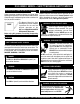
HERE'S HOW TO GET HELP PLEASE HAVE THE MODEL AND SERIAL NUMBER ON-HAND WHEN CALLING MQ POWER CORPORATE OFFICE 18910 Wilmington Ave. 800-421-1244 Carson, CA 90746 FAX: 310-632-2656 Email: mqpower@multiquip.com Internet: www.mqpower.com PARTS DEPARTMENT 800-427-1244 FAX: 800-672-7877 310-537-3700 FAX: 310-637-3284 SERVICE DEPARTMENT 800-835-2551 FAX: 310-638-8046 310-537-3700 TECHNICAL ASSISTANCE 800-835-2551 FAX: 310-638-8046 WARRANTY DEPARTMENT 800-835-2551, EXT. 279 FAX: 310-638-8046 310-537-3700, EXT.
TABLE OF CONTENTS MQPower DCA-300SSK SERIES AC Generator California Proposition 65 Warning ..................................... 2 Here's How To Get Help .................................................... 3 Table Of Contents ............................................................. 4 Parts Ordering Procedures ............................................... 5 Specifications Generator/Engine ...................................... 6 Dimensions (Top, Side and Front) .....................................
PARTS ORDERING PROCEDURES When ordering parts, please supply the following information: ❒ ❒ ❒ ❒ ❒ ❒ ❒ Dealer account number Dealer name and address Shipping address (if different than billing address) Return fax number Applicable model number Quantity, part number and description of each part Specify preferred method of shipment: ✓FedEx or UPS Ground Note: Unless otherwise indicated by customer, all ✓FedEx or UPS Second Day or Third Day orders are treated as “Standard Orders”, and will ✓FedEx or UPS Next D
DCA-300SSK SERIES — SPECIFICATIONS Table 1. Generator Specifications Design No. of Poles Excitation Standby Output Prime Output Generator RPM Voltage — 3Ø Voltage — 1Ø Armature Connection Voltage Regulation (No load to full load) Power Factor Frequency Frequency Regulation: No load to full load Frequency Regulation: Steady State Insulation Sound Level dB(A) Full load at 23 feet Dimensions Approx.
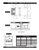
DCA-300SSK SERIES — DIMENSIONS (TOP, SIDE AND FRONT) Figure 1. Dimensions TABLE 3. DIMENSIONS Reference Letter Dimension in. (mm.) Reference Letter Dimension in. (mm.) A 42.32 in. (1,075 mm.) F 42.32 in. (1,075 mm.) B 39.96 in. (1,015 mm.) G 147.64 in. (3,750 mm.) C 25.20 in. (640 mm.) H 70.98 in. (1,800 mm.) D 23.03 in. (585 mm.) I 55.12 in. (1,400 mm.) E 39.96 in. (1,015 mm.) DCA-300SSK SERIES — PARTS AND OPERATION MANUAL (STD)— REV.
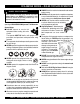
DCA-300SSK SERIES — SAFETY MESSAGE ALERT SYMBOLS FOR YOUR SAFETY AND THE SAFETY OF OTHERS! Safety precautions should be followed at all times when operating this equipment. Failure to read and understand the Safety Messages and Operating Instructions could result in injury to yourself and others. NOTE This Owner's Manual has been developed to provide complete instructions for the safe and efficient operation of the MQ Power Model DCA-400SSVU Whisperwatt™ Generator.
DCA-300SSK SERIES — SAFETY MESSAGE ALERT SYMBOLS WARNING - ROTATING PARTS NEVER operate equipment with covers, or guards removed. Keep fingers, hands, hair and clothing away from all moving parts to prevent injury. CAUTION - ACCIDENTAL STARTING ALWAYS place the Engine ON/OFF switch in the OFF position and remove the ignition key when the pump is not in use. CAUTION - OVER-SPEED CONDITIONS NEVER tamper with the factory settings of the engine governor or settings.
DCA-300SSK SERIES — RULES FOR SAFE OPERATION DANGER - READ THIS MANUAL! Failure to follow instructions in this manual may lead to serious injury or even DEATH! This equipment is to be operated by trained and qualified personnel only! This equipment is for industrial use only. The following safety guidelines should always be used when operating the DCA-400SSVU Whisperwatt™ AC Generator. General Safety: ■ ALWAYS check the machine for loosened threads or bolts before starting.
DCA-300SSK SERIES — RULES FOR SAFE OPERATION Generator Grounding To guard against electrical shock and possible damage to the equipment, it is important to provide a good EARTH ground. Article 250 (Grounding) of the National Electrical Code (NEC) provides guide lines for proper grounding and specifies that the cable ground shall be connected to the grounding system of the building as close to the point of cable entry as practical.
DCA-400SSVU — RULES FOR SAFE OPERATION Maintenance Safety ■ The electrical voltage required to operate the generator can cause severe injury or even death through physical contact with live circuits. Turn all circuit breakers OFF before performing maintenance on the generator. ■ NEVER lubricate components or attempt service on a running machine. ■ ALWAYS disconnect the NEGATIVE battery terminal before performing service on the generator.
DCA-400SSVU — RULES FOR SAFE OPERATION Towing & Transporting Safety ■ The maximum speed for highway towing is 55 MPH unless posted otherwise. Recommended off-road towing To reduce the possibility of an accident while transporting is not to exceed 15 MPH or less depending on type of the generator on public roads, always make sure the trailer terrain.
DCA-300SSK SERIES — GENERATOR DECALS The DCA-300SSK generator is equipped with a number of safety decals (Figures 2 & 3). These decals are provided for operator safety and maintenance information. The illustration below and on the preceding pages show the decals as they appear on the machine. Should any of these decals become unreadable, replacements can be obtained from your dealer. Figure 2. Generator Decals PAGE 14 — DCA-300SSK SERIES — PARTS AND OPERATION MANUAL (STD) — REV.
DCA-300SSK SERIES — GENERATOR DECALS Figure 3. Generator Decals DCA-300SSK SERIES — PARTS AND OPERATION MANUAL (STD)— REV.
DCA-300SSK SERIES — INSTALLATION Figure 4. Typical Generator Grounding Application PAGE 16 — DCA-300SSK SERIES — PARTS AND OPERATION MANUAL (STD) — REV.
DCA-300SSK SERIES — INSTALLATION Outdoor Installation Generator Grounding Install the generator in a area that is free of debris, bystanders, and overhead obstructions. Make sure the generator is on secure level ground so that it cannot slide or shift around. Also install the generator in a manner so that the exhaust will not be discharged in the direction of nearby homes. To guard against electrical shock and possible damage to the equipment, it is important to provide a good EARTH ground.
DCA-300SSK SERIES — GENERAL INFORMATION DCA-300SSK FAMILIARIZATION Open Delta Excitation System The DCA-300SSK series generators are equipped with the The MQ Power DCA-300SSK series generators are 240 kW state of the art "Open-Delta" excitation system. The open generators that are designed as a high quality portable delta system consist of an electrically independent winding (requires a trailer for transport) power source for telecom wound among stationary windings of the AC output section.
DCA-300SSK SERIES — MAJOR COMPONENTS Figure 5. Major Components Table 4. Generator Major Components ITEM NO. DESCRIPTION 1 Muffler Assembly 2 Engine Assembly 3 Enclosure Assembly 4 Generator Assembly 5 Output Terminal Assembly 6 Battery Assembly 7 Fuel Tank Assembly 8 Generator Control Panel Assembly 9 Engine Operating Panel Assembly DCA-300SSK SERIES — PARTS AND OPERATION MANUAL (STD)— REV.
DCA-300SSK — GENERATOR CONTROL PANEL S/N 3701673 and Below S/N 3701674 and Above Figure 6. Generator Control Panel PAGE 20 — DCA-300SSK SERIES — PARTS AND OPERATION MANUAL (STD) — REV.
DCA-300SSK — GENERATOR CONTROL PANEL The definitions below describe the controls and functions of the DCA-300SSK “Control Panel” (Figure 8). 1. Pilot Lamp – Indicates that the generator is working properly. 2. Panel Light – Normally used in dark areas or at night time. When activated, panel lights will illuminate. When the generator is not in use be sure to turn the panel light switch to the OFF position. 3. Frequency Meter – Indicates the output frequency in hertz (Hz). Normally 60 Hz ±1 Hz . 4.
DCA-300SSK — ENGINE OPERATING PANEL S/N 3701673 and Below S/N 3701674 and Above Figure 7. Engine Operating Panels PAGE 22 — DCA-300SSK SERIES — PARTS AND OPERATION MANUAL (STD) — REV.
DCA-300SSK — ENGINE OPERATING PANEL The definitions below describe the controls and functions of the DCA-300SSK or DCA-300SSK2 “Engine Operating Panels” (Figure 7). 1. Throttle Handle - This handle controls the speed of the engine (low or high). 2. Tachometer – Indicates engine speed in RPM’s for 60 Hz operation. This meter should indicate 1800 RPM’s when the rated load is applied. In addition a built in hour meter will record the number of operational hours that the generator has been in use. 3.
DCA-300SSK SERIES — OUTPUT TERMINAL PANEL FAMILIARIZATION Output Terminal Familiarization Output Terminal Panel The “Output Terminal Panel ” (Figure 8) is provided with Shown below (Figure 8) is the Output Terminal Panel , lift up on the cover to gain access to receptacles and terminal the following: lugs.
DCA-300SSK SERIES — OUTPUT TERMINAL PANEL FAMILIARIZATION 120 VAC GFCI Receptacles There are two 120 VAC, 20 amp GFCI (Duplex Nema 5-20R) recepacles provided on the output terminal panel. These receptacles can be accessed in any voltage change-over board position. Each receptacle is protected by a 20 amp circuit breaker. These breakers are located directly above the GFCI receptacles. Remember the load output (current) of both GFCI receptacles is dependent on the load requirements of the UVWO terminals.
DCA-300SSK SERIES — OUTPUT TERMINAL PANEL FAMILIARIZATION Connecting Loads Loads can be connected to the generator by the UVWO terminal lugs or the convenience receptacles. (See Figure 12). Make sure to read the operation manual before attempting to connect a load to the generator. To protect the UVWO output terminals from overload, a 3pole, 800 amp, main circuit breaker is provided. Make sure to switch ALL circuit breakers to the "OFF" position prior to starting the engine.
DCA-300SSK SERIES — LOAD APPLICATION Single Phase Load Always be sure to check the nameplate on the generator and equipment to insure the wattage, amperage and frequency requirements are satisfactorily supplied by the generator for operating the equipment. Generally, the wattage listed on the nameplate of the equipment is its rated output.
DCA-300SSK SERIES — GENERATOR OUTPUTS Generator Output Voltages Generator Amperage A wide range of voltages are available to supply voltage for Tables 8 and 9 describe the generator’s current output capamany different applications. Voltages are selected by applybility for both 1Ø-phase and 3Ø phase applications. ing jumpers (6) to the voltage change-over board (Figure 14). To obtain some of the voltages as listed in Table 7 (see Table 8.
DCA-300SSK SERIES — GENERATOR OUTPUTS/GAUGE READING Maximum Amps Table 10 shows the maximum amps the generator can provide. DO NOT exceed the maximum amps as listed. Table 10. Generator Maximum Amps Model: DCA300SSK Series Rated Voltage Maximum Amps Single Phase 120 Volt 2000 amps (4 wire) Single Phase 240 Volt 1000 amps (4 wire) Three Phase 240 Volt 720 amps Three Phase 480 Volt 360 amps How to Read the Output Terminal Gauge.
DCA-300SSK SERIES — OUTPUT TERMINAL PANEL CONNECTIONS UVWO Terminal Output Voltages Various output voltages can be obtained using the UVWO output terminal lugs. The voltages at the terminals are dependent on the placement of the jumpers plates (6) on the Voltage Change-Over Board and the adjustment of the Figure 22. Voltage Regulator Knob Voltage Regulator Control Knob.
DCA-300SSK SERIES — OUTPUT TERMINAL PANEL CONNECTIONS 3Ø-480V UVWO Terminal Output Voltages 1Ø-480V UVWO Terminal Output Voltages 1. Jumper the voltage change-over board for 480V operation 1. Make sure the voltage change-over board is jumpered as shown in Figure 25. This configuration uses 6 jumper for 480V operation as shown in Figure 25. plates in 3 different positions. Remember there are 2 2. Connect the load wires to the UVWO terminals as shown jumper plates at every position.
DCA-300SSK SERIES — PRE-SETUP Circuit Breakers Fuel Check To protect the generator from an overload, a 3-pole, 800 amp, main circuit breaker is provided to protect the UVWO output terminals from overload. In addition two single-pole, 20 amp GFCI circuit breakers are provided to protect the GFCI receptacles from overload. Three 50 amp load circuit breakers have also been provided to protect the auxiliary receptacles from overload.
DCA-300SSK SERIES — PRE-SETUP CAUTION - REFUELING TRAILER FUEL TANK ALWAYS! fill trailer tank first with #2 diesel fuel, before filling secondary internal tank. Figure 31. Skid Type Fuel Tank System Refueling Procedure: WARNING - RESPIRATORY HAZARDS Diesel fuel and its vapors are dangerous to your health and the surrounding environment. Avoid skin contact and/or inhaling fumes. 1. Level Tanks – make sure fuel cells are level with the ground.
DCA-300SSK SERIES — PRE-SETUP 3. NEVER overfill trailer fuel tank – It is important to 5. read the trailer fuel gauge when filling trailer fuel tank. DO NOT wait for fuel to rise in filler neck. See Figure 34. Figure 34. Full Trailer Tank CAUTION - REFUELING THE GENERATOR DO NOT OVER-FILL fuel system. Leave room for fuel expansion. Fuel expands when heated. Figure 36 below reflects a full fuel system. Figure 36. Full Fuel System 6.
DCA-300SSK SERIES — PRE-SETUP Coolant (Ethylane Glycol [Green] / Water — 50/50 mix) Use only drinkable tap water. If hard water or water with many impurities is used, the inside of the engine and radiator may become coated with deposits and cooling efficiency will be reduced. An anticorrosion additive added to the water will help prevent deposits and corrosion in the cooling system. See the engine manual for further details.
DCA-300SSK SERIES — PRE-SETUP Battery This unit is of negative ground DO NOT connect in reverse. Always maintain battery fluid level between the specified marks. Battery life will be shortened, if the fluid level are not properly maintained. Add only distilled water when replenishment is necessary. DO NOT over fill. Check to see whether the battery cables are loose. Poor contact may result in poor starting or malfunctions. Always keep the terminals firmly tightened.
DCA-300SSK SERIES — GEN. START-UP PROCEDURE (MANUAL) BEFORE STARTING (S/N 3701673 and below) NOTE 1. Place the main, G.F.C.I. and aux. circuit breakers (Figure 42) in the “OFF” position prior to starting the engine. Steps 1 thru 20 are referenced for Engine Operating Panel S/N 3701673 and below. See Figure 40 below. This unit has an ignition switch and a throttle handle. Figure 42. Main, Aux. and GFCI Circuit Breakers (OFF) Figure 40.
DCA-300SSK SERIES — GENERATOR START-UP PROCEDURE (MANUAL) 6. Set the battery ON/OFF switch (Figure 43) to the “ON” 12. The generator's frequency meter (Figure 48) should be position. displaying the 60 cycle output frequency in HERTZ. Figure 43. Battery ON/OFF Switch 7. When starting the generator in COLD weather conditions, turn the ignition key to the “PREHEAT ” position (Figure 44). Figure 48. Frequency Meter (Hz) 13.
DCA-300SSK SERIES — GENERATOR START-UP PROCEDURE (MANUAL) 15. The engine oil pressure gauge (Figure 52) will indicate the oil pressure (kg/ cm2) of the engine. Under normal operating conditions the oil pressure is approximately 0 4 kg/cm2 18. Place the main, GFCI, and aux. circuit breakers in the “ON” position (Figure 55). 8 ENGINE OIL PRESSURE Figure 52. Oil Pressure Gauge 16. The coolant temperature gauge (Figure 53) will indicate the coolant temperature.
DCA-300SSK SERIES — GENERATOR START-UP PROCEDURE (MANUAL) BEFORE STARTING (S/N 3701674 and above) 4. Place the engine speed switch in the “LOW ” position (Figure 60). Steps 1 thru 8 are referenced for Engine Operating Panel S/N 3701674 and above. See Figure 57 below. This unit does Figure 60. Engine Speed Switch (Low) not have an ignition switch or a throttle handle. It does have an “engine speed switch” that is 5.
DCA-300SSK SERIES — GEN. START-UP PROCEDURE (AUTO MODE) When starting generator in AUTO mode use the "Manual Start-up" procedure except where noted (see below). Starting (Auto Mode) DANGER - ELECTRICAL SYSTEM HAZARDS Before connecting this generator to any building’s electrical system, a licensed electrician must install an isolation (transfer) switch. Serious damage to the building’s electrical system may occur without this transfer switch. 1.
DCA-300SSK SERIES — GEN. SHUT-DOWN PROCEDURE (MANUAL) Engine Shutdown Ignition Key (Up to S/N 3701673) To shutdown the generator use the following procedure: 1. Place both the MAIN, GFCI and LOAD circuit breakers (Figure 67) to the "OFF position". Engine Shutdown Controller (S/N 3701674~) To shutdown the generator use the following procedure: 1. Place both the MAIN, GFCI and LOAD circuit breakers as shown in Figure 67 to the "OFF position". 2.
NOTE PAGE DCA-300SSK SERIES — PARTS AND OPERATION MANUAL (STD)— REV.
DCA-300SSK SERIES — MAINTENANCE Use Table 13 shown below as a general checklist to be performed on a daily basis. TABLE 13.
DCA-300SSK SERIES — MAINTENANCE General Inspection Prior to each use, the generating set should be cleaned and inspected for deficiencies. Check for loose, missing or damaged nuts, bolts or other fasteners. Also check for fuel or oil leaks. Air Cleaner Every 50 hours: If dust indicator is RED, clean the air cleaner element. Fuel Addition Add diesel fuel (the grade may vary according to season and locations). Always pour through the mesh filter.
WARNING - BURN HAZARDS DCA-300SSK SERIES — MAINTENANCE DCA-300SSK SERIES — MAINTENANCE 14. Drain the water inside reserve tank, clean the inside of Allow engine to cool when flushing out radiator. Flushing the radiator while hot could cause serious burns from water or steam. the reserve tank, then fill with coolant/water mixture to between the full and low lines. 15. Stop the engine, wait for 3 minutes, add tap water until the water level reaches near the water filer port, then tighten the radiator cap.
DCA-300SSK SERIES — MAINTENANCE 5. After replacing filter cartridge, loosen air bleed plug. Generator Storage: 6. Loosen the knob of feed pump, and pump it up and down until no bubbles come out with the fuel from air bleed plug. For storage of the generator for over 30 days, the following is required: z Fill the fuel tank completely. Treat with fuel stabilizer if 7. After bleeding the air, tighten air bleed plug, then push in necessary. the knob of feed pump and lock it in position.
DCA-300SSK SERIES — MAINTENANCE Jacket Water Heater and Internal Battery Charger 120 VAC Input Receptacles (OPTIONAL) This generator is equipped with two 120 VAC, 20 amp input receptacles located on the output terminal panel. The purpose of these receptacles is to provide power via commercial power to the jacket water heater and internal battery charger. These receptacles will ONLY function when commercial power has been supplied to them (Figure 73).
DCA-300SSK SERIES —TRAILER MAINTENANCE Trailer Maintenance 8. Tire Size - Indicates the diameter of the tire in inches (10,12,14, etc.), and the width in millimeters This section is intended to provide the user with generic (175,185,205, etc.). The tire diameter must match the trailer service and maintenance information. The service and diameter of the tire rim. maintenance guidelines referenced in this section refer to a wide range of trailers. 9.
DCA-300SSK SERIES —TRAILER MAINTENANCE Brakes Trailer brakes should be inspected the first 200 miles of operation. This will allow the brake shoes and drums to seat properly. After the first 200 mile interval, inspect the brakes every 3,000 miles. If driving over rough terrain, inspect the brakes more frequently. Figure 74 displays the major hydraulic surge brake components that will require inspection and maintenance. Use Table 14 as a basic trouble shooting guide when brake problems occur.
DCA-300SSK SERIES —TRAILER MAINTENANCE Tires/Wheels/Lug Nuts Tires and wheels are a very important and critical components of the trailer. When specifying or replacing the trailer wheels it is important the wheels, tires, and axle are properly matched. CAUTION - EYESIGHT HAZARD Suspension The leaf suspension springs and associated components (Figure 75) should be visually inspected every 6,000 miles for signs of excessive wear, elongation of bolt holes, and loosening of fasteners.
DCA-300SSK SERIES —TRAILER MAINTENANCE Lug Nut Torque Requirements It is extremely important to apply and maintain proper wheel mounting torque on the trailer. Be sure to use only the fasteners matched to the cone angle of the wheel. Proper procedure for attachment of the wheels is as follows: 1. Start all wheel lug nuts by hand. 2. Torque all lug nuts in sequence. See Figure 77. DO NOT torque the wheel lug nuts all the way down. Tighten each lug nut in 3 separate passes as defined by Table 17. 3.
DCA-300SSK — TRAILER-WIRING DIAGRAM Figure 77. Trailer/Towing Vehicle Wiring Diagram DCA-300SSK SERIES — PARTS AND OPERATION MANUAL (STD)— REV.
DCA-300SSK — GENERATOR WIRING DIAGRAM Figure 78. Generator Wiring Diagram PAGE 54 — DCA-300SSK SERIES — PARTS AND OPERATION MANUAL (STD) — REV.
DCA-300SSK— ENGINE WIRING DIAGRAM (S/N 3696506 AND BELOW) Figure 79. Engine Wiring Diagram (S/N 3696506 and Below) DCA-300SSK SERIES — PARTS AND OPERATION MANUAL (STD)— REV.
DCA-300SSK — ENGINE WIRING DIAGRAM (S/N3696507 TO 3701673) Figure 80. Engine Wiring Diagram (S/N 3696507-3701673) PAGE 56 — DCA-300SSK SERIES — PARTS AND OPERATION MANUAL (STD) — REV.
DCA-300SSK — ENGINE WIRING DIAGRAM (S/N 3701674 AND ABOVE) Figure 81. Engine Wiring Diagram (S/N 3701674 and Above) DCA-300SSK SERIES — PARTS AND OPERATION MANUAL (STD)— REV.
DCA-300SSK — TROUBLESHOOTING (ENGINE) Practically all breakdowns can be prevented by proper handling and maintenance inspections, but in the event of a breakdown, use Table 18 (Engine Troubleshooting) as a basic guideline for troubleshooting the engine. If the problem cannot be remedied, consult our company's business office or service plant. TABLE 18. ENGINE TROUBLESHOOTING SYMPTOM Engine does not star t. POSSIBLE PROBLEM SOLUTION No fuel? Replenish fuel. Air in the fuel system? Bleed system.
DCA-300SSK — TROUBLESHOOTING (ENGINE) TABLE 18. ENGINE TROUBLESHOOTING (CONTINUED) SYMPTOM Engine revolution is not smooth. Either white or blue exhaust gas is observed. Either black or dark gray exhaust gas is observed. Deficient output. POSSIBLE PROBLEM SOLUTION Fuel filter clogged or dir ty? Clean or change. Air cleaner clogged? Clean or change. Fuel leak due to loose injection pipe retaining nut? Tighten nut. Injection pump malfunctioning? Repair or replace.
DCA-300SSK — TROUBLESHOOTING (GENERATOR) Practically all breakdowns can be prevented by proper handling and maintenance inspections, but in the event of a breakdown, use Table 19 (Generator Troubleshooting) as a basic guideline for troubleshooting the generator. If the problem cannot be remedied, consult our company's business office or service plant. TABLE 19. GENERATOR TROUBLESHOOTING SYMPTOM POSSIBLE PROBLEM SOLUTION AC Voltmeter defective? Check output voltage using a voltmeter.
DCA-300SSK — TROUBLESHOOTING (ENGNE CONTROLLER) TABLE 20. ENGINE CONTROLLER TROUBLESHOOTING (MPEC) Sympton Low oil pressure light is on. Low coolant level light is on. High coolant temper ture light is on. Possible Cause Solution Low oil level? Fill oil level. Oil pressure sending unit failure? Replace oil pressure sending unit. Time delay malfuntion in Controller? Refer to dealer. Wire shor ted? Inspect/repair wire. Low coolant level? Fill coolant level.
EXPLANATION OF CODE IN REMARKS COLUMN The following section explains the different symbols and remarks used in the Parts section of this manual. Use the help numbers found on the back page of the manual if there are any questions. The contents and part numbers listed in the parts section are subject to change without notice . Multiquip does not guarantee the availibility of the parts listed. PART NO. PART NAME QTY. 12345 BOLT ....................... 1.... WASHER, 1/4 IN. ........... 12347 WASHER, 3/8 IN.
DCA-300SSK — SUGGESTED SPARE PARTS DCA-300SSK W/KOMATSU SA6D125E-2/ SAA6D125E-2 1 to 5 Units Qty. P/N Description 10 .............. 6125817032 .....................AIR FILTER, INNER & OUTER 10 .............. 6003118321 .....................FUEL FILTER 10 .............. 6002111231 .....................OIL FILTER 5 ................ 6004111151 .....................CARTRIDGE, CORROSION RESISTOR 3 ................ 0810105400 .....................FUEL FILTER, FUEL TANK 2 ................ xxxxxxxxxx ..............
DCA-300SSK GENERATOR ASSY. GENERATOR ASSY. PAGE 64 — DCA-300SSK SERIES — PARTS AND OPERATION MANUAL (STD) — REV.
DCA-300SSK GENERATOR ASSY. GENERATOR ASSY. NO. 1 2 * 3 * 4 * 5 * 5 * 5 * 6 * 7 * 8 * 9 * 10 * 11 * 12 * 13 * 14 * 15 16 17 18 18 19 20 21 22 23 24 25 25 26 27 28 29 30 31 32 33 33 33 34 35 36 37 37 37 PART NO.
DCA-300SSK GENERATOR ASSY. GENERATOR ASSY. PAGE 66 — DCA-300SSK SERIES — PARTS AND OPERATION MANUAL (STD) — REV.
DCA-300SSK GENERATOR ASSY. GENERATOR ASSY.(CONT) NO. 38 39 40 40 41 41 42 42 42 43 44 44 PART NO. C3154400003 0017106016 0012112035 0042512000 C3132300003 C3132300014 0010106030 0041206000 0600815000 0605000012 0030020000 0040020000 PART NAME QTY. REMARKS SUCTION COVER 1 HEX. HEAD BOLT 8 HEX. HEAD BOLT 16 LOCK WASHER 16 COVER, FAN ................................................... 1 ......... S/N3691259 TO 3692208 COVER, FAN ................................................... 1 .........
DCA-300SSK CONTROL BOX ASSY. CONTROL BOX ASSY. PAGE 68 — DCA-300SSK SERIES — PARTS AND OPERATION MANUAL (STD) — REV.
DCA-300SSK CONTROL BOX ASSY. CONTROL BOX ASSY. NO. PART NO. PART NAME QTY. REMARKS 1 C2214000102 CONTROL BOX .............................................. 1 ............... S/N 3691259 TO 3706720 1 C2214001502 CONTROL BOX .............................................. 1 ............... S/N 3706721 AND ABOVE 2 0601806134 CURRENT TRANSFORMER .......................... 3 ............... CT-5MR500/5A 3 0027106016 MACHINE SCREW 6 4 0601807373 CIRCUIT BREAKER,XS800NS800A .............. 1 ...............
DCA-300SSK CONTROL BOX ASSY. CONTROL BOX ASSY. (CONT) PAGE 70 — DCA-300SSK SERIES — PARTS AND OPERATION MANUAL (STD) — REV.
DCA-300SSK CONTROL BOX ASSY. CONTROL BOX ASSY. (CONT) NO. 29 30 31 32 32 33 34 35 36 37 38 39 39 40 41 42 42 43 44 45 46 47 47 47 47 48 49 50 51 52 53 54 55 56 57 58 59 60 PART NO.
DCA-300SSK CONTROL BOX ASSY. CONTROL BOX ASSY. (CONT) PAGE 72 — DCA-300SSK SERIES — PARTS AND OPERATION MANUAL (STD) — REV.
DCA-300SSK CONTROL BOX ASSY. CONTROL BOX ASSY. (CONT) NO. 61 62 62 62 63 63 63 63 64 65 65 65 65 66 67 68 69 70 71 72 72 73 73 74 75 76 77 78 PART NO. 0601823240 0021004030 0040004000 0041204000 0601802149 0601802149 0601806671 0601802218 0027103020 0601823732 0601827655 0601823109 0601824400 0027104020 0601823706 0027104015 0601815402 0027104020 ECU9988N300/400 0601831340 0601830765 DYNT11200 0602202470 DYN110654000024 0027104020 0601840009 C3262600004 0017106015 PART NAME QTY.
DCA-300SSK ENGINE & RADIATOR ASSY. (S/N 3697258 AND BELOW) ENGINE & RADIATOR ASSY. (S/N 3697258 AND BELOW) PAGE 74 — DCA-300SSK SERIES — PARTS AND OPERATION MANUAL (STD) — REV.
DCA-300SSK ENGINE & RADIATOR ASSY. (S/N 3697258 AND BELOW) ENGINE & RADIATOR ASSY. (S/N 3697258 AND BELOW) NO. 1 PART NO.
DCA-300SSK ENGINE & RADIATOR ASSY. (UP TO S/N3697258) ENGINE & RADIATOR ASSY. (UP TO S/N3697258) PAGE 76 — DCA-300SSK SERIES — PARTS AND OPERATION MANUAL (STD) — REV.
DCA-300SSK ENGINE & RADIATOR ASSY. (UP TO S/N3697258) ENGINE & RADIATOR ASSY. (UP TO S/N3697258) NO. 41 42 43 44 45 46 47 48 49 50 51 PART NO. 0603320112 0038408000 0268200700 0605515132 C2358300103 0017110020 C2358300003 0017108020 0010016030 0040016000 0041216000 PART NAME U BOLT HEX. NUT HOSE HOSE BAND CLAMPER ROD HEX. HEAD BOLT CLAMPER ROD HEX. HEAD BOLT HEX. HEAD BOLT LOCK WASHER PLAIN WASHER QTY. 1 2 1 2 1 2 1 1 1 1 1 REMARKS DCA-300SSK SERIES — PARTS AND OPERATION MANUAL (STD)— REV.
DCA-300SSK ENGINE & RADIATOR ASSY. (S/N 3708270 TO 3708296) ENGINE & RADIATOR ASSY. (S/N3691259 TO S/N 3708296) PAGE 78 — DCA-300SSK SERIES — PARTS AND OPERATION MANUAL (STD) — REV.
DCA-300SSK ENGINE & RADIATOR ASSY. (S/N 3708270 TO 3708296) ENGINE & RADIATOR ASSY. (S/N3691259 TO S/N 3708296) NO. PART NO.
DCA-300SSK ENGINE & RADIATOR ASSY. (S/N 3708270 AND ABOVE) ENGINE & RADIATOR ASSY. (S/N 3708270 AND ABOVE) PAGE 80 — DCA-300SSK SERIES — PARTS AND OPERATION MANUAL (STD) — REV.
DCA-300SSK ENGINE & RADIATOR ASSY. (S/N 3708270 AND ABOVE) ENGINE & RADIATOR ASSY. (S/N 3708270 AND ABOVE) NO. 1 1-1 1-2 1-3 1-4 1-5 2 3 4 5 6 7 8 9 10 11 12 13 14 15 16 17 18 19 20 21 22 23 24 25 26 27 28 29 29 PART NO.
DCA-300SSK ENGINE & RADIATOR ASSY. (S/N 3708270 AND ABOVE) ENGINE & RADIATOR ASSY. (S/N 3708270 AND ABOVE) PAGE 82 — DCA-300SSK SERIES — PARTS AND OPERATION MANUAL (STD) — REV.
DCA-300SSK ENGINE & RADIATOR ASSY. (S/N 3708270 AND ABOVE) ENGINE & RADIATOR ASSY. (S/N 3708270 AND ABOVE) NO. 30 31 32 33 34 35 36 37 38 39 40 41 42 43 44 45 46 47 48 49 50 PART NO.
DCA-300SSK ENGINE OPERATING PANEL ASSY. ENGINE OPERATING PANEL ASSY. S/N3701674~ UP TO S/N3701673 PAGE 84 — DCA-300SSK SERIES — PARTS AND OPERATION MANUAL (STD) — REV.
DCA-300SSK ENGINE OPERATING PANEL ASSY. ENGINE OPERATING PANEL ASSY. NO. 1 1 1 2 2 3 4 5 5 5 5 6 7 7 8 9 10 11 12 13 13 14 15 16 17 18 19 20 21 22 23 24 25 26 27 28 29 30 31 32 33 34 35 36 PART NO.
DCA-300SSK OUTPUT TERMINAL ASSY. OUTPUT TERMINAL ASSY. UP TO S/N3691258 S/N3691259~ PAGE 86 — DCA-300SSK SERIES — PARTS AND OPERATION MANUAL (STD) — REV.
DCA-300SSK OUTPUT TERMINAL ASSY. OUTPUT TERMINAL ASSY. NO. 1 1 PART NO. C2231700203 8221860203 PART NAME QTY. REMARKS SET BOARD, OUTPUT TERMINAL ................ 1 ......... S/N 3708296 AND BELOW SET BOARD, OUTPUT TERMINAL ................ 1 .........
DCA-300SSK OUTPUT TERMINAL ASSY. OUTPUT TERMINAL ASSY. UP TO S/N3691258 S/N3691259~ PAGE 88 — DCA-300SSK SERIES — PARTS AND OPERATION MANUAL (STD) — REV.
DCA-300SSK OUTPUT TERMINAL ASSY. OUTPUT TERMINAL ASSY. NO. 21 22 23 23 23 24 25 26 27 28 29 30 31 32 34 35 36 PART NO. 020501200 0845043704 C2237100504 C2237100514 C2237101204 0017108020 C0237101504 0805015604 0845054204 0017110040 0601815324 0027104020 0601850275 0601851780 C2237101504 C2237400104 0017106020 PART NAME QTY. REMARKS HEX. NUT 2 SPRING 2 COVER ............................................................ 1 ......... S/N 1337508 TO 3691258 COVER ................................................
DCA-300 SSK ACTUATOR ASSY. ACTUATOR ASSY. (S/N3701674~) PAGE 90 — DCA-300SSK SERIES — PARTS AND OPERATION MANUAL (STD) — REV.
DCA-300 SSK ACTUATOR ASSY. ACTUATOR ASSY. (S/N 3701674~) NO. 1 2 3 4 5 5 5 5 6 7 8 9 9 9 10 10 10 PART NO. DYNC110240000024 DYNC182 C1356200004 0012310030 0010306035 0207006000 0040006000 0041206000 0602211091 0602180190 0602211092 0010106025 0207006000 0041206000 0010106025 0207006000 0041206000 PART NAME QTY. REMARKS ACTUATOR ....................................... 1 ............. REPLACES 0602150091 LEVER ............................................. 1 .............
DCA-300 SSK BATTERY ASSY. BATTERY ASSY. PAGE 92 — DCA-300SSK SERIES — PARTS AND OPERATION MANUAL (STD) — REV.
DCA-300 SSK BATTERY ASSY. BATTERY ASSY. NO. 1 2 3 4 5 6 7 8 9 10 11 12 13 14 15 16 17 PART NO. 0168614551 0805000804 3972250004 0805002904 0037808000 0040008000 0041208000 C2347600404 C2347600104 C2347600204 C2347600304 C2347200004 0010010030 0030010000 0845040414 0845041304 0602220204 PART NAME BATTERY BATTERY SHEET BATTERY BAND BATTERY BOLT WING NUT LOCK WASHER PLAIN WASHER BATTERY CABLE BATTERY CABLE BATTERY CABLE BATTERY CABLE EARTH CABLE HEX. HEAD BOLT HEX.
DCA-300SSK MUFFLER ASSY. MUFFLER ASSY. PAGE 94 — DCA-300SSK SERIES — PARTS AND OPERATION MANUAL (STD) — REV.
DCA-300SSK MUFFLER ASSY. MUFFLER ASSY. NO. 1 2 3 3 PART NO. C2331100002 0019210025 C2334000003 C2234000503 PART NAME QTY. REMARKS MUFFLER 1 HEX. HEAD BOLT 4 EXHAUST PIPE .............................................. 1 ......... UP TO S/N 3708296 EXHAUST PIPE .............................................. 1 .........
DCA-300SSK FUEL TANK ASSY. FUEL TANK ASSY. PAGE 96 — DCA-300SSK SERIES — PARTS AND OPERATION MANUAL (STD) — REV.
DCA-300SSK FUEL TANK ASSY. FUEL TANK ASSY. NO. 1 1 2 2 3 4 4 5 6 7 8 9 10 10 11 12 13 14 15 16 17 18 19 20 21 21 22 22 23 PART NO. C2364000303 C2364000313 0605505030 0601850590 0810105400 0264100485 0264100525 0605515079 0605503023 0802120604 0605501050 0602021155 0027104010 0022905015 8195523104 0805003414 0017108020 0037908000 0222100300 0130206000 3515512014 0603325011 0132006000 0845039604 0191302000 0191302300 0191302240 0191302800 0605515109 PART NAME QTY. REMARKS FUEL TANK .........................
DCA-300SSK ENCLOSURE ASSY. (UP TO S/N 3708296) ENCLOSURE ASSY. (UP TO S/N 3708296) THE PART NUMBER ABOVE INDICATES DEFAULT COLOR OF ORANGE. TO ORDER WITH DIFFERENT COLOR, PLEASE ADD THE FOLLOWING LETTERS WITH THE PART NUMBER: MQGR-GRAY MQGRN-GREEN MQW-WHITE THE SERIAL NUMBER MAY BE REQUIRED. PAGE 98 — DCA-300SSK SERIES — PARTS AND OPERATION MANUAL (STD) — REV.
DCA-300SSK ENCLOSURE ASSY. (UP TO S/N 3708296) ENCLOSURE ASSY. (UP TO S/N 3708296) NO. 1 1 1 2 3 4 5 5 6 7 7 7 7 8 9 10 10 11 12 13 14 15 16 16 17 17 17 17 18 18 18 18 19 19 20 21 22 22 23 23 24 25 25 26 27 PART NO.
DCA-300SSK ENCLOSURE ASSY. (UP TO S/N 3708296) ENCLOSURE ASSY. (UP TO S/N 3708296) THE PART NUMBER ABOVE INDICATES DEFAULT COLOR OF ORANGE. TO ORDER WITH DIFFERENT COLOR, PLEASE ADD THE FOLLOWING LETTERS WITH THE PART NUMBER: MQGR-GRAY MQGRN-GREEN MQW-WHITE THE SERIAL NUMBER MAY BE REQUIRED. PAGE 100 — DCA-300SSK SERIES — PARTS AND OPERATION MANUAL (STD) — REV.
DCA-300SSK ENCLOSURE ASSY. (UP TO S/N 3708296) ENCLOSURE ASSY. (UP TO S/N 3708296) NO. 28 29 30 31 32 33 34 35 35 36 37 38 39 40 41 42 43 43 44 44 45 46 47 48 48 49 50 50 50 51 51 52 53 53 53 53 53 53 54 54 54 55 55 56 56 PART NO.
DCA-300SSK ENCLOSURE ASSY. (UP TO S/N 3708296) ENCLOSURE ASSY. (UP TO S/N 3708296) THE PART NUMBER ABOVE INDICATES DEFAULT COLOR OF ORANGE. TO ORDER WITH DIFFERENT COLOR, PLEASE ADD THE FOLLOWING LETTERS WITH THE PART NUMBER: MQGR-GRAY MQGRN-GREEN MQW-WHITE THE SERIAL NUMBER MAY BE REQUIRED. PAGE 102 — DCA-300SSK SERIES — PARTS AND OPERATION MANUAL (STD) — REV.
DCA-300SSK ENCLOSURE ASSY. (UP TO S/N 3708296) ENCLOSURE ASSY. (UP TO S/N 3708296) NO. 57 57 58 58 59 59 60 60 61 61 62 62 63 64 65 66 66 67 67 68 68 69 70 71 72 73 74 75 76 PART NO.
DCA-300SSK ENCLOSURE ASSY. (S/N 3708297~) ENCLOSURE ASSY. (S/N 3708297~) THE PART NUMBER ABOVE INDICATES DEFAULT COLOR OF ORANGE. TO ORDER WITH DIFFERENT COLOR, PLEASE ADD THE FOLLOWING LETTERS WITH THE PART NUMBER: MQGR-GRAY MQGRN-GREEN MQW-WHITE THE SERIAL NUMBER MAY BE REQUIRED. PAGE 104 — DCA-300SSK SERIES — PARTS AND OPERATION MANUAL (STD) — REV.
DCA-300SSK ENCLOSURE ASSY. (S/N 3708297~) ENCLOSURE ASSY. (S/N 3708297~) NO. 1 2 3 4 5 5 6 7 7 8 9 10 10 11 12 13 14 15 16 17 17 17 17 18 18 18 18 19 19 20 21 22 22 23 23 24 25 25 26 27 28 29 30 31 32 33 PART NO.
DCA-300SSK ENCLOSURE ASSY. (S/N 3708297~) ENCLOSURE ASSY. (S/N 3708297~ THE PART NUMBER ABOVE INDICATES DEFAULT COLOR OF ORANGE. TO ORDER WITH DIFFERENT COLOR, PLEASE ADD THE FOLLOWING LETTERS WITH THE PART NUMBER: MQGR-GRAY MQGRN-GREEN MQW-WHITE THE SERIAL NUMBER MAY BE REQUIRED. PAGE 106 — DCA-300SSK SERIES — PARTS AND OPERATION MANUAL (STD) — REV.
DCA-300SSK ENCLOSURE ASSY. (S/N 3708297~) ENCLOSURE ASSY. (S/N 3708297~) NO. 34 35 35 36 37 38 39 40 41 42 43 43 44 44 45 46 47 48 48 49 50 50 50 51 51 52 53 54 54 54 55 55 56 56 57 57 58 58 59 59 60 60 61 61 62 62 PART NO.
DCA-300SSK ENCLOSURE ASSY. (S/N 3708297~) ENCLOSURE ASSY. (S/N 3708297~) THE PART NUMBER ABOVE INDICATES DEFAULT COLOR OF ORANGE. TO ORDER WITH DIFFERENT COLOR, PLEASE ADD THE FOLLOWING LETTERS WITH THE PART NUMBER: MQGR-GRAY MQGRN-GREEN MQW-WHITE THE SERIAL NUMBER MAY BE REQUIRED. PAGE 108 — DCA-300SSK SERIES — PARTS AND OPERATION MANUAL (STD) — REV.
DCA-300SSK ENCLOSURE ASSY. (S/N 3708297~) ENCLOSURE ASSY. (S/N 3708297~) NO. 63 64 65 66 66 67 67 68 68 69 70 71 72 73 74 75 77 78 79 PART NO.
DCA-300SSK RUBBER SEAL ASSY. RUBBER SEAL ASSY. PAGE 110 — DCA-300SSK SERIES — PARTS AND OPERATION MANUAL (STD) — REV.
DCA-300SSK RUBBER SEAL ASSY. RUBBER SEAL ASSY. NO. 1 2 3 4 5 6 7 7 8 9 10 PART NO. 0228901250 0228901090 0228900650 0228901030 0229201400 0229201300 0228800705 0221200705 0228801200 0228100120 0228100510 PART NAME QTY. REMARKS RUBBER SEAL 6 RUBBER SEAL 4 RUBBER SEAL 2 RUBBER SEAL 4 RUBBER SEAL 4 RUBBER SEAL 1 RUBBER SEAL ............................................... 2 ......... S/N3691259 TO 3701673 RUBBER SEAL ............................................... 2 .........
DCA-300SSK OIL PIPING ASSY. OIL PIPING ASSY. PAGE 112 — DCA-300SSK SERIES — PARTS AND OPERATION MANUAL (STD) — REV.
DCA-300SSK OIL PIPING ASSY. OIL PIPING ASSY. NO. 1 2 3 4 5 6 7 8 9 10 11 12 PART NO. 0602023040 C2324400004 0017110025 0017106025 7522054204 0131506000 0120006005 3972027104 0191600900 0605515074 0193301200 0605515004 PART NAME PUMP BRACKET, PUMP HEX., HEAD BOLT HEX., HEAD BOLT BUSHING NIPPLE VALVE HOSE JOINT HOSE HOSE BAND HOSE HOSE BAND QTY. 1 1 2 5 1 1 1 2 1 2 1 1 REMARKS DCA-300SSK SERIES — PARTS AND OPERATION MANUAL (STD)— REV.
DCA-300SSK NAMEPLATE AND DECALS NAMEPLATE AND DECALS PAGE 114 — DCA-300SSK SERIES — PARTS AND OPERATION MANUAL (STD) — REV.
DCA-300SSK NAMEPLATE AND DECALS NAMEPLATE AND DECALS NO. PART NO. PART NAME 1 0800655603 DECAL; HANDLING PROCED.; S2763A 1 C155100503 DECAL; HANDLING PROCED.; C1510050 1 C155200403 DECAL; HANDLING PROCED.; C1520040 2 B155200103 DECAL; CAUTION; B15200010 2 C952210003 DECAL; CAUTION; C92210000 3 4 5 6 7 8 9 10 11 12 13 14 15 19 19 20 20 21 22 23 23 5-1 5-2 5-3 5-4 5-5 5-6 5-7 5-8 QTY.
DCA-300SSK NAMEPLATE AND DECALS NAMEPLATE AND DECALS PAGE 116 — DCA-300SSK SERIES — PARTS AND OPERATION MANUAL (STD) — REV.
DCA-300SSK NAME PLATE AND DECALS NAMEPLATE AND DECALS NO. PART NO. 16 17 18 6360610304 B9504000404 B9504100104 PART NAME QTY. REMARKS ENGINE & RADIATOR GROUP DECAL; WATER ......................................................... 1............ S-1880 DECAL; WARNING .................................................... 2............ B90400040 DECAL; WARNING .................................................... 1............
DCA-300SSK NAMEPLATE AND DECALS NAMEPLATE AND DECALS PAGE 118 — DCA-300SSK SERIES — PARTS AND OPERATION MANUAL (STD) — REV.
DCA-300SSK NAMEPLATE AND DECALS NAMEPLATE AND DECALS NO. 39 40 41 42 43 44 45 46 46 47 47 48 49 50 50 51 PART NO. PART NAME QTY. REMARKS 1320610603 1320621504 0840625902 B9504000304 B9531100604 C2561101003 C2561101603 C2561101303 C2561102003 C2561101404 C2561102103 C2561101204 C2561101803 C2561101503 C2561102203 C2561101703 ENCLOSURE GROUP DECAL; WATER-OIL .................................................. 1............ S-1760 DECAL; SUPPORT HOOK ........................................ 2............
TERMS AND CONDITIONS OF SALE — PARTS Effective: October 1, 2002 PAYMENT TERMS 5. Parts must be in new and resalable condition, in the original Multiquip package (if any), and with Multiquip part numbers clearly marked. 6. The following items are not returnable: Terms of payment for parts are net 30 days. FREIGHT POLICY All parts orders will be shipped collect or prepaid with the charges added to the invoice. All shipments are F.O.B. point of origin.
NOTE PAGE DCA-300SSK SERIES — PARTS AND OPERATION MANUAL (STD)— REV.
OPERATION AND PARTS MANUAL HERE'S HOW TO GET HELP PLEASE HAVE THE MODEL AND SERIAL NUMBER ON-HAND WHEN CALLING PARTS DEPARTMENT 800-427-1244 or 310-537-3700 FAX: 800-672-7877 or 310-637-3284 SERVICE DEPARTMENT 800-421-1244 FAX: 310- 537-4259 TECHNICAL ASSISTANCE 800-478-1244 FAX: 310- 631-5032 WARRANTY DEPARTMENT 888-661-4279, or 310-661-4279 FAX: 310- 537-1173 Manufactured for Multiquip Inc. by DENYO CO., LTD, JAPAN MULTIQUIP INC.