OPERATION AND PARTS MANUAL MODELS DA7000SS-DA7000SSA DA700SSW-DA7000WGH PORTABLE GENERATORS (KUBOTA Z482 SERIES DIESEL ENGINES) Revision #5 (01/20/11) To find the latest revision of this publication, visit our website at: www.multiquip.com THIS MANUAL MUST ACCOMPANY THE EQUIPMENT AT ALL TIMES.
PROPOSITION 65 WARNING Diesel engine exhaust and some of PAGE 2 — DA7000 SERIES GENERATORS• OPERATION AND PARTS MANUAL — REV.
REPORTING SAFETY DEFECTS If you believe that your vehicle has a defect that could cause a crash or could cause injury or death, you should immediately inform the National Highway Traffic Safety Administration (NHTSA) in addition to notifying Multiquip at 1-800-421-1244. If NHTSA receives similar complaints, it may open an investigation, and if it finds that a safety defect exists in a group of vehicles, it may order a recall and remedy campaign.
TABLE OF CONTENTS DA7000 SERIES GENERATOR Proposition 65 Warning .................................................. 2 Reporting Safety Defects................................................ 3 Table Of Contents ........................................................... 4 Parts Ordering Procedures ............................................. 5 Safety Information ..................................................... 6-11 Specifications (Generator) ............................................
www.multiquip.com PARTS ORDERING PROCEDURES Ordering parts has never been easier! Choose from three easy options: Order via Internet (Dealers Only): Best Deal! Effective: January 1st, 2006 If you have an MQ Account, to obtain a Username and Password, E-mail us at: parts@multiquip. com. Order parts on-line using Multiquip’s SmartEquip website! ■ View Parts Diagrams ■ Order Parts ■ Print Specification Information To obtain an MQ Account, contact your District Sales Manager for more information.
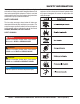
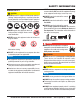
SAFETY INFORMATION Do not operate or service the equipment before reading the entire manual. Safety precautions should be followed at all times when operating this equipment. Failure to read and understand the safety messages and operating instructions could result in injury to yourself and others. Potential hazards associated with the operation of this equipment will be referenced with hazard symbols which may appear throughout this manual in conjunction with safety messages.
SAFETY INFORMATION GENERAL SAFETY CAUTION NEVER operate this equipment without proper protective clothing, shatterproof glasses, respiratory protection, hearing protection, steel-toed boots and other protective devices required by the job or city and state regulations. NEVER operate this equipment when not feeling well due to fatigue, illness or when under medication. NEVER operate this equipment under the influence of drugs or alcohol.
SAFETY INFORMATION ENGINE SAFETY DANGER The engine fuel exhaust gases contain poisonous carbon monoxide. This gas is colorless and odorless, and can cause death if inhaled. The engine of this equipment requires an adequate free flow of cooling air. NEVER operate this equipment in any enclosed or narrow area where free flow of the air is restricted. If the air flow is restricted it will cause injury to people and property and serious damage to the equipment or engine.
SAFETY INFORMATION FUEL SAFETY DANGER DO NOT start the engine near spilled fuel or combustible fluids. Diesel fuel is extremely flammable and its vapors can cause an explosion if ignited. Make sure the hitch and coupling of the towing vehicle are rated equal to, or greater than the trailer “gross vehicle weight rating.” ALWAYS inspect the hitch and coupling for wear. NEVER tow a trailer with defective hitches, couplings, chains, etc.
SAFETY INFORMATION ELECTRICAL SAFETY DANGER DO NOT touch output terminals during operation. Contact with output terminals during operation can cause electrocution, electrical shock or burn. The electrical voltage required to operate the generator can cause severe injury or even death through physical contact with live circuits. Turn generator and all circuit breakers OFF before performing maintenance on the generator or making contact with output terminals.
SAFETY INFORMATION BATTERY SAFETY DANGER DO NOT drop the battery. There is a possibility that the battery will explode. DO NOT expose the battery to open flames, sparks, cigarettes, etc. The battery contains combustible gases and liquids. If these gases and liquids come into contact with a flame or spark, an explosion could occur. ENVIRONMENTAL SAFETY NOTICE Dispose of hazardous waste properly. Examples of potentially hazardous waste are used motor oil, fuel and fuel filters.
SPECIFICATIONS (GENERATOR) Table 1. Specifications (Generator) Model Type Excitation Speed Cooling System Max Power Output AC Generator 60 Hz AC Power Source Continuous Power Output Rated Voltage Current Max/Continuous (120V) Current Max/Continuous (240V) Phase Frequency Power Factor Battery Dimensions (L x W x H) Dry Net Weight DA7000SS/DA7000SSA DA7000SSW/DA7000SSWGH 2-Pole Brushless Revolving Field Type Solid State, Statically Excited System 3,600 RPM Self-Ventilation 7 kW 6 kW 120/240V 58.3/50 amps 29.
SPECIFICATIONS (ENGINE) Engine Dimensions (L x W x H) Dry Net Weight Table 2. Specifications (Engine) Kubota Engine Model Z482-EB Z482-E2B-DGDE-2 Z482-E3B-DGDE-2 Tier 1 2 4 Gen. Enclosure Color Orange Orange/White White Type Vertical, water-cooled, 4-cycle diesel engine 2.64 in. X 2.68 in. Bore X Stroke (67 mm x 68 mm.) Displacement 29.23 cu.-in. (479 cm3) Number of Cylinders 2 Max Output 12.5~13.9 H.P./3600 R.P.M. Fuel #2 Diesel Fuel Fuel Capacity 6.6 gal. (25 liters) Fuel Consumption .7 gals. (2.
DIMENSIONS Figure 1. Dimensions PAGE 14 — DA7000 SERIES GENERATORS• OPERATION AND PARTS MANUAL — REV.
NOTE DA7000 SERIES GENERATORS • OPERATION AND PARTS MANUAL — REV.
INSTALLATION CONNECTING THE GROUND The nut and ground terminal on the generator should always be used to connect the generator to a suitable ground. The ground cable should be #8 size wire minimum. At the generator, connect the terminal of the ground cable between the lock washer and the nut (Figure 2) and tighten the nut fully. Connect the other end of the ground cable to a suitable earth ground (ground rod). DANGER THE POSSIBILITY EXISTS OF ELECTROCUTION IF GENERATOR/WELDER IS NOT PROPERLY GROUNDED.
INSTALLATION OUTDOOR INSTALLATION GENERATOR GROUNDING If possible install the generator in a area that is free of debris, bystanders, and overhead obstructions. Make sure the generator is on secure level ground so that it cannot slide or shift around. To guard against electrical shock and possible damage to the equipment, it is important to provide a good EARTH ground. The installation site must be relatively free from moisture and dust.
GENERAL INFORMATION FAMILIARIZATION Oil Pressure Warning Alarm Generator This unit is equipped with a protective device that detects low oil pressure. If the lubricating oil pressure of this unit should become abnormally low, the protective device will automatically stop the engine. If this condition should occur, please refer to the engine troubleshooting table in this manual. The Multiquip DA7000 Series generators are 6.0 kW (continuous output), 7.0 kW (max output) A.C.
COMPONENTS (GENERATOR) Figure 3. Generator Components 1. Fuel Gauge — Indicates the amount of fuel in the fuel tank. 10. Automatic Speed Control Solenoid — Automatically regulates engine speed. 2. Air Outlet Exhaust — Allows engine exhaust to exit the generator into the open air. NEVER block this opening. 11. Battery Terminals — Connect these terminals to the battery. Always pay close attention to the polarity of the terminals when connecting to the battery, RED (positive), and BLACK (negative). 3.
COMPONENTS (GENERATOR) below the rated voltage, engine problems may exist (low/high RPM's). To prevent damage to the generator or power tools turn the generator OFF and consult your authorized Multiquip service dealer. 26. Hour Meter — Indicates number of hours machine has been in use or hours engine was run. 27. Idle Control Switch — The generator is provided with an automatic idle control device for noise suppression and reduced fuel consumption. Figure 4. Generator Components 17.
COMPONENTS (ENGINE) Figure 5. Kubota Z482 Series INITIAL SERVICING The engine (Figure 5) must be checked for proper lubrication and filled with fuel prior to operation. Refer to the manufacturer's engine manual for instructions and details of operation and servicing. 1. Water Drain Cock — Open this cock to drain water 2. Fuel Filter — Prevents dirt and other debris from entering the fuel system. Replace filter as recommended in the maintenance section of this manual. 3.
LOAD APPLICATIONS Single Phase Load — 60 Hz Always be sure to check the nameplate on the generators and equipment to insure the wattage, amperage and frequency requirements are satisfactorily supplied by the generators for operating the equipment. Generally, the wattage listed on the nameplate of the equipment is its rated output. Equipment may require 130—150% more wattage than the rating on the nameplate, as the wattage is influenced by the efficiency, power factor and starting system of the equipment.
INSPECTION/SETUP GENERAL INSPECTION PRIOR TO OPERATION Ground Power Tools When using power tools or electrical equipment requireing AC power from the generator, make sure power tool cord has a ground pin or is double insulated as shown in Figure 6. NOTICE Double-insulated power tools and small appliances have specially insulated housings that eliminate the need for a ground.
INSPECTION/SETUP Before Starting 1. Read safety instructions at the beginning of manual. 2. Clean the generator, removing dirt and dust, particularly the engine cooling air inlet. 4. If the oil level is low, remove the oil filler cap (Figure 9) and fill to a safe operating level (max) as indicated by the dipstick. Fill with recommended type oil as listed in Table 5. Maximum oil capacity is 2.64 quarts (2.5 liters). 3. Check the air filter for dirt and dust.
INSPECTION/SETUP NOTICE NOTICE When adding engine oil DO NOT overfill. When refueling, be sure to use a strainer for filtration. DO NOT top-off fuel. DO NOT fill the tank beyond capacity. Wipe up any spilled fuel immediately! Fuel Check Fill the fuel tank with #2 diesel fuel. DO NOT fill the tank beyond capacity. Pay attention to the fuel tank capacity when replenishing fuel. Refer to the fuel tank capacity listed in Table 2. The fuel tank cap must be closed tightly after filling.
INSPECTION/SETUP BATTERY NOTICE When the antifreeze is mixed with water, the antifreeze mixing ratio must be less than 50%. CLEANING THE RADIATOR The engine may overheat if the radiator fins become overloaded with dust or debris. Periodically clean the radiator fins with compressed air. Cleaning inside the machine is dangerous, so clean only with the engine turned off and the negative battery terminal disconnected. AIR CLEANER Periodic cleaning/replacement is necessary.
INSPECTION/SETUP When connecting battery do the following: 1. NEVER connect the battery cables to the battery terminals when the Ignition Switch is in the START position. ALWAYS make sure that the Ignition Switch is in the OFF position when connecting the battery. 2. Place a small amount of battery terminal treatment compound around both battery terminals. This will ensure a good connection and will help prevent corrosion around the battery terminals.
OPERATION 3. NEVER start the engine with the main circuit breaker in the ON position. Always place circuit breaker (Figure 16) in the OFF position before starting. Before Starting the Engine CAUTION The engine’s exhaust contains harmful emissions. ALWAYS have adequate ventilation when operating. Direct exhaust away from nearby personnel. WARNING OFF OFF 25A 25A NEVER manually start the engine with the main or GFCI circuit breakers in the ON (closed) position. Figure 16. Main Circuit Breaker (OFF) 1.
OPERATION 4. If the engine does not start within 10 seconds after the key is turned to the START position, wait for about 30 seconds and repeat the procedure as described in step 4. above. 5. When the engine starts, the oil pressure light and charge light should go out. If these lights stay on, immediately stop the engine and check the system and wiring (refer to the Engine Operation Manual). 6. Let the engine idle for five minutes with the Idle Control Switch (Figure 19) placed in the ON position. 2.
OPERATION/SHUTDOWN 4. The CS-6369 receptacle is a dual voltage receptacle (120/240 volts). Using an external voltmeter as shown in Figure 23, verify that 120/240 VAC is present at the CS-6369 twist-lock receptacle.. Stopping the Engine (Normal Shutdown) 1. Place main circuit breaker (Figure 25) in the OFF position. OFF OFF 25A 25A Figure 25. Main Circuit Breaker (OFF) 2. Place GFCI circuit breakers (Figure 26) in the OFF positing. Figure 26. GFCI Circuit Breakers (OFF) Figure 23.
PREPARATION FOR LONG TERM STORAGE Generator Storage For storage of the generating set for over 30 days, the following is required: Run the engine until all the fuel is completely consumed. Drain the fuel tank completely, or add STA-BIL to the fuel Completely drain the oil from the crankcase and refill with fresh oil. Disconnect the negative battery cable from the battery. Clean all external parts of the generating set with a cloth.
MAINTENANCE Use Table 8as a general maintenance guideline when servicing your engine. For more detail engine maintenance information, refer to the engine owner's manual supplied with your engine. Table 8. Engine Maintenance Schedule DESCRIPTION (3) OPERATION DAILY Engine Oil CHECK CHANGE X Oil Filter Cartridge CHANGE Air Cleaner Element All Nuts & Bolts CHECK CHANGE RETIGHTEN IF NECESSARY CHECK CLEAN CLEAN FIRST EVERY 3 MONTH OR MONTHS 50 HRS. OR 25 HRS. EVERY 6 MONTHS OR 50 HRS.
MAINTENANCE Maintenance Perform the scheduled maintenance procedures as defined by Table 8 and below: Engine Oil Every 100 hours: Change engine oil after the first 50 hours of operation and 100 hours thereafter. Always check the crankcase oil level prior to each use, or when the fuel tank is filled. Insufficient oil may cause severe engine damage. Make sure generator is level when checking oil level. The oil level must be between the two notches on the dipstick as shown in Figure 8. 1.
MAINTENANCE Cleaning the Fuel Filter Radiator Every 100 hours: Clean fuel filter every 100 hours of operation or once a month to remove dust or water. Check Daily: Always check the level of the coolant in the radiator before starting the engine. Remove the radiator cap and verify that the coolant reaches top of radiator coils. 1. Place fuel cock lever (Figure 32) in the close position. 2. Disconnect fuel lines from fuel filter. 1. DO NOT remove the radiator cap while the coolant is hot.
MAINTENANCE 2. Flush the radiator by running clean tap water through radiator until signs of rust and dirt are removed. DO NOT clean radiator core with any objects, such as a screwdriver. GENERATOR STORAGE For long term storage of the generator the following is recommended: 3. Check hoses for softening and kinks. Check clamps for signs of leakage. Drain the fuel tank completely. Treat with a fuel stabilizer if necessary. 4. Tighten coolant drain plug and reinstall the overflow tank.
MAINTENANCE (TRAILER) TRAILER MAINTENANCE The following trailer maintenance guidelines are intended to assist the operator in preventive maintenance. Adjustable Channel Your trailer may be equipped with an adjustable channel (Figure I) that allows the coupler to be raised or lowered to a desired height. Periodically check the channel bolts for damage or loosening. Follow the steps below to disassemble the wheel hub and service the wheel bearings. See Figure II.
MAINTENANCE (TRAILER) DANGER NEVER crawl under the trailer unless it is on firm and level ground and resting on properly placed and secured jackstands. The possibility exists of the trailer falling thus causing equipment damage and severe bodily harm even death! Leaf Suspension The leaf suspension springs and associated components (Figure III) should be visually inspected every 6,000 miles for signs of excessive wear, elongation of bolt holes, and loosening of fasteners.
TRAILER GUIDELINES The following guidelines are intended to assist the operator in the operation and handling of a trailer. Shift your automatic transmission into a lower gear for city driving. Safety precautions should be followed at all times when operating a trailer. Failure to read, understand and follow the safety guidelines could result in injury to yourself and others. Loss of control of the trailer or tow vehicle can result in death or serious injury.
TRAILER GUIDELINES DRIVING CONDITIONS When towing a trailer, you will have decreased acceleration, increased stopping distance, and increased turning radius (which means you must make wider turns to keep from hitting curbs, vehicles, and anything else that is on the inside corner). In addition, you will need a longer distance to pass, due to slower acceleration and increased length. Be alert for slippery conditions.
TRAILER GUIDELINES INOPERABLE BRAKES, LIGHTS OR MIRRORS Be sure that the brakes and all of the lights on your trailer are functioning properly before towing your trailer. Check the trailer taillights by turning on your tow vehicle headlights. Check the trailer brake lights by having someone step on the tow vehicle brake pedal while you look at trailer lights. Do the same thing to check the turn signal lights. See Trailer Wiring Diagram section in this manual.
TRAILER GUIDELINES To determine the “empty” or “net” weight of your trailer, weigh it on an axle scale. To find the weight of the trailer using an axle scale, you must know the axle weights of your tow vehicle without the trailer coupled. Some of the trailer weight will be transferred from the trailer to the tow vehicle axles, and an axle scale weighs all axles, including the tow vehicle axles. G VIN TA TOW VEHICLE VIN TAG Figure B.
TRAILER GUIDELINES SAFETY CHAINS If the coupler connection comes loose, the safety chains can keep the trailer attached to the tow vehicle. With properly rigged safety chains, it is possible to keep the tongue of the trailer from digging into the road pavement, even if the coupler-to-hitch connection comes apart. JACKSTAND A device on the trailer that is used to raise and lower the coupler. The jack is sometimes called the “landing gear” or the “tongue jack”.
TRAILER GUIDELINES WARNING Lower the trailer (Figure D) until the coupler fully engages the hitch ball. A worn, cracked or corroded hitch ball can fail while towing and may result in death or serious injury. 2-INCH TRAILER COUPLER TOW VEHICLE Before coupling trailer, inspect the hitch ball for wear, corrosion and cracks. Replace worn or damaged hitch ball. 2-INCH BALL WARNING A loose hitchball nut can result in uncoupling, leading to death or serious injury.
TRAILER GUIDELINES Attaching Safety Chain Backup Lights (place tow vehicle gear shift in reverse). Visually inspect the safety chains and hooks for wear or damage. Replace worn or damaged safety chains and hooks before towing. Turn Signals (activate tow vehicle directional signal lever). Attach the safety chains so that they: • Cross underneath the coupler. See Figure E.
TRAILER GUIDELINES PINTLE HITCH COUPLER A pintle eye coupler (Figure F) connects to a pintle-hook hitch that is located on or under the rear bumper of the tow vehicle. This system of coupling a trailer to a tow vehicle is sometimes referred to as a “lunette eye, tow ring or G.I. hitch.
TRAILER GUIDELINES Raise the bottom surface of the coupler to be above the top of the pintle hitch hook. Use the tongue jackstand to support the trailer tongue. Wood or concrete blocks may also be used. WARNING Lower the trailer so that its entire tongue weight is held by the hitch. Raise the jackstand to a height where it will not interfere with the road. TIRE SAFETY A defective pintle hitch not properly fastened can result in uncoupling, leading to death or serious injury.
TRAILER GUIDELINES wrench, use a lug wrench (from your tow vehicle) and tighten the nuts as much as you can. Then have a service garage or trailer dealer tighten the lug nuts to the proper torque. WARNING Metal creep between the wheel rim and lug nuts will cause rim to loosen and could result in a wheel coming off, leading to death or serious injury. Tighten lug nuts before each tow. Lug nuts are also prone to loosen after first being assembled.
TRAILER GUIDELINES Step 2. Determine the weight of the equipment being loaded on the tow vehicle. That weight may not safely exceed the available equipment load capacity. The trailer’s Tire Information Placard is attached adjacent to or near the trailer’s VIN (Certification) label at the left front of the trailer (See Figure I). along with other care and maintenance activities, can also: Locate the statement, “The combined weight of occupants and cargo should never exceed XXX lbs.
TRAILER GUIDELINES Next number: This two-digit number is the wheel or rim diameter in inches. If you change your wheel size, you will have to purchase new tires to match the new wheel diameter. in the tire. In general, the greater the number of plies, the more weight a tire can support. Tire manufacturers also must indicate the materials in the tire, which include steel, nylon, polyester, and others. Next number: This two- or three-digit number is the tire’s load index.
TRAILER GUIDELINES Tires for light trucks have other markings besides those found on the sidewalls of passenger tires. LT: The “LT” indicates the tire is for light trucks or trailers. ST: An “ST” is an indication the tire is for trailer use only. Max. Load Dual kg (lbs) at kPa (psi) Cold: This information indicates the maximum load and tire pressure when the tire is used as a dual, that is, when four tires are put on each rear axle (a total of six or more tires on the vehicle). Max.
TRAILER GUIDELINES Wheel Rims If the trailer has been struck, or impacted, on or near the wheels, or if the trailer has struck a curb, inspect the rims for damage (i.e. being out of round); and replace any damaged wheel. Inspect the wheels for damage every year, even if no obvious impact has occurred. 3.
TRAILER WIRING DIGRAM Figure 37. Trailer Wiring Diagram PAGE 52 — DA7000 SERIES GENERATORS• OPERATION AND PARTS MANUAL — REV.
GENERATOR WIRING DIGRAM Figure 38. Generator Wiring Diagram (DA7000 SERIES) DA7000 SERIES GENERATORS • OPERATION AND PARTS MANUAL — REV.
ENGINE WIRING DIGRAM Figure 39. Engine Wiring Diagram PAGE 54 — DA7000 SERIES GENERATORS• OPERATION AND PARTS MANUAL — REV.
TROUBLESHOOTING (ENGINE AND GENERATOR) Table 9. Engine and Generator Troubleshooting SYMPTOM Engine fails to start and starter does not rotate. Engine fails to start and starter rotates. Engine starts "Idle Control Switch" is in OFF position and engine remains at low speed. Engine starts and "Idle Control Switch" is in OFF position. Engine speed rises and no voltage is present in AC power source. POSSIBLE PROBLEM SOLUTION Dead Battery? Replace Battery. Defective Starter Switch? Replace Switch.
TROUBLESHOOTING (ENGINE AND GENERATOR) Table 9. Engine and Generator Troubleshooting (Continued) SYMPTOM POSSIBLE PROBLEM SOLUTION Engine starts and "Idle Control Switch" is in OFF position. Engine speed rises and battery discharges too soon. Defective Engine Regulator? Replace Regulator. Defective Wiring? Repair or Replace Wiring. Engine starts and "Idle Control Switch" is in OFF position. Engine speed rises and engine seems overloaded. Defective Alternator? Repair or Replace Alternator.
TROUBLESHOOTING (ENGINE) SYMPTOM Engine does not start. Table 10.
TROUBLESHOOTING (ENGINE) Table 10. Engine Troubleshooting (Continued) SYMPTOM POSSIBLE PROBLEM SOLUTION Fuel filter clogged or dirty? Clean or change. Air cleaner clogged? Clean or change. Fuel leak due to loose injection pipe retaining Tighten nut. nut? Engine revolution is not smooth Either white or blue exhaust gas is observed. Either black or dark gray exhaust gas is observed. Deficient output. Injection pump malfunctioning? Repair or replace. Incorrect nozzle opening pressure? Adjust.
NOTES DA7000 SERIES GENERATORS • OPERATION AND PARTS MANUAL — REV.
EXPLANATION OF CODE IN REMARKS COLUMN The following section explains the different symbols and remarks used in the Parts section of this manual. Use the help numbers found on the back page of the manual if there are any questions. NOTICE The contents and part numbers listed in the parts section are subject to change without notice. Multiquip does not guarantee the availability of the parts listed. SAMPLE PARTS LIST NO. 1 2% 2% 3 4 PART NO. PART NAME QTY. REMARKS 12345 BOLT .....................1 .....
SUGGESTED SPARE PARTS DA7000 SERIES GENERATORS WITH KUBOTA Z482-EB/Z482-E2B/ Z482-E3B DIESEL ENGINES 1 to 3 units NOTICE Part numbers on this Suggested Spare Parts list may supersede/replace the part numbers shown in the following parts lists. Qty. P/N Description 5............1556211010..........AIR FILTER 5............7000011221..........AIR FILTER, ELEMENT 5............1523143560..........FUEL FILTER 5............7000015241..........OIL FILTER CARTRIDGE, Z482-EB/Z482-E2B ENGINES 5............
NAMEPLATE AND DECALS ASSY. F3 5A F2 5A F1 30A 1. Maintain water/coolant level at top of radiator coils. WATER COOLANT LEVEL 2. Maintain reserve tank water/ coolant level between H and L mark. Use a mixture of 50/50 Anti-Freeze/Water. 10 3. Add coolant when reserve tank is low (L). Fill to the H mark with Anti-Freeze/Water. WARNING! Before connecting this generator to any building’s electrical system, a licensed electrician must install an isolation [transfer] switch.
NAMEPLATE AND DECALS ASSY. NO. 1 2# 3# 4# 5# 6# 6# 7# 8# 9# 10# 11# 12# 13# 14# 15# 16# 16# 17# 17# 18# 19# 20# 21# 22# 22# 23# 24# 25# 25# 26# 27# 28# 29# 30# 31# 32# 33# 34 35 36 PART NO.
GENERATOR ASSY. PAGE 64 — DA7000 SERIES GENERATORS• OPERATION AND PARTS MANUAL — REV.
GENERATOR ASSY. NO. 1 1-1# 1-2# 1-3# 1-4# 1-5# 1-6# 1-7# 2 3 4 5 6 7 8 9 10 11 11 12 13 14 14A PART NO. A5110100003 A5116000103 7871025004 042006304 A5113100002 0171707033 1991072004 0012308020 011208025 A515510002 A5136000103 A6155000002C 7871329514 7901316004 0040008000 031108160 A6155400104C 0027106012 0027105012 0012308020 0805084704 020108060 0801086104 PART NAME QTY. REMARKS ROTOR ASSY. ...................................................1................INCLUDES ITEMS W/# FIELD ASSY.
CONTROL PANEL ASSY. PAGE 66 — DA7000 SERIES GENERATORS• OPERATION AND PARTS MANUAL — REV.
CONTROL PANEL ASSY. NO. 1 1 2 3 4 5 6 7 8 9 9A 10 10A 11 12 12A 13 14 15 16 17 17A 18 19 20 PART NO. A5225000303 A5511302402 0021805020 0601800258 0207003000 0601807456 4341817004 0021004016 0601830771 1628663602 3741055150 0601810523 0601810830 0601800682 0027403512 0030003500 0601811034 0601812529 0601811031 0601812597 0021004010 0030004000 0601806420 0027103005 0601815109 PART NAME QTY. REMARKS CONTROL PANEL 1 CONTROL PANEL .............................................1................
ELECTRIC PARTS ASSY. PAGE 68 — DA7000 SERIES GENERATORS• OPERATION AND PARTS MANUAL — REV.
ELECTRIC PARTS ASSY. NO. 1 2 3 4 5 6 7 8 9 10 11 12 13 14 15 16 16A 16B 16C 17 18 19 20 21 22 23 24 25 25A 26 27 28 29 30 31 32 33A 33 34 35 PART NO.
ENGINE AND RADIATOR ASSY. PAGE 70 — DA7000 SERIES GENERATORS• OPERATION AND PARTS MANUAL — REV.
ENGINE AND RADIATOR ASSY. NO. 1 1 1 1A 1-1 1-1 2 3 4 5 6 6 6-1# 6-1% 7 8 9 10 11 11 12 13 13A 14 14A 15 16 17 18 19 20 21 22 23 24 25 PART NO.
ENGINE AND RADIATOR ASSY. PAGE 72 — DA7000 SERIES GENERATORS• OPERATION AND PARTS MANUAL — REV.
ENGINE AND RADIATOR ASSY. NO. 26 27 28 29 30 31 31 32 33 34 35 36 37 38 38 39 40 41 42 43 44 45 45 46 PART NO. 0802011104 0150000018 0016906016 D2322400004 0199900550 0199900700 0199900500 0605515094 0805010004 1552053004 0602021190 0192200400 0605515081 0605515003 0605515159 0802081403 0602081104 1622082104 0016906025 0016906016 7222016304 0199900650 0199900650 0605515094 PART NAME QTY. REMARKS PLUG 2 O-RING A P18 2 HEX HEAD BOLT 4 HOSE JOINT 1 DRAIN HOSE 1 DRAIN HOSE 1 DRAIN HOSE........................
BATTERY ASSY. PAGE 74 — DA7000 SERIES GENERATORS• OPERATION AND PARTS MANUAL — REV.
BATTERY ASSY. NO. 1 2 3 4 5 6 7 8 9 10 PART NO. 0167103820 1702202104 D2345200004 0805082704 0037806000 0040006000 0041206000 0602220310 0602220311 0602220600 PART NAME BATTERY BATTERY SHEET BATTERY BAND BATTERY BOLT WING NUT WASHER, LOCK WASHER, FLAT TERMINAL ASSY. (POSITIVE) TERMINAL ASSY. (NEGATIVE) TERMINAL CAP QTY. 1 1 1 2 2 2 2 1 1 1 REMARKS DA7000 SERIES GENERATORS • OPERATION AND PARTS MANUAL — REV.
MUFFLER ASSY. PAGE 76 — DA7000 SERIES GENERATORS• OPERATION AND PARTS MANUAL — REV.
MUFFLER ASSY. NO. 1 2 3 4 5 6 7 PART NO. D2332100003 0016908020 D2335000003 1526312371 1502336004 0207008000 0016908035 PART NAME QTY. REMARKS MUFFLER 1 HEX. HEAD BOLT 4 EXHAUST PIPE 1 GASKET ............................................................1................REPLACES 1526312371 GASKET 1 HEX. NUT 4 HEX. HEAD BOLT 2 DA7000 SERIES GENERATORS • OPERATION AND PARTS MANUAL — REV.
FUEL TANK ASSY. PAGE 78 — DA7000 SERIES GENERATORS• OPERATION AND PARTS MANUAL — REV.
FUEL TANK ASSY. NO. 1 1A 1B 2 3 4 5 6 7 8 8 9 10 11 12 13 14 15 15A 16 17 18 19 20 21 22 23 24 PART NO. D2365000013 0810105800 0810105900 0602125033 D2365200004 0805003414 0016906016 0207308000 D1490600104 1615511204 B9312400004A 7812014003 0802011104 0150000018 0016906016 0199900670 0605515094 1553143010 1523143560 D2368700004 0016906016 0016908065 0966180240 0966180400 0966140320 0966140240 1491142750 1024442320 PART NAME QTY.
OIL FILTER RETROFIT ASSY. WHISPERWATT 7KW AC Model DA-700 0SS ON AC CIRCUI T BREAKER 7000 WATT DIESEL POWE RED OFF IDLE CONTROL AC VOLTM ETER STOP RUN HEAT START 00000 HOURS AC GENER ATOR HOUR METER STARTER SWITCH 20A 25A 120V 25A 25A 120/240V PART OF ENCLOSURE 10 12 9 15 8 13 7 6 4 3 ENGINE PAGE 80 — DA7000 SERIES GENERATORS• OPERATION AND PARTS MANUAL — REV.
OIL FILTER RETROFIT ASSY. NO. 3 4 6 7# 8# 9 10 12 13 15 PART NO. 148002003 010601000 149149001 DA7000NUT DA7000LOCKWASHER DA7000BOLT 149002000 7000015241 PART NAME QTY. REMARKS ADAPTER FILTER 1 HOSE KIT 1 BRACKET ................................. 1 ............... INCLUDES ITEMS W/# BOLT ......................................... 4 ............... NOT SOLD SEPARATELY LOCKWASHER ......................... 4 ...............
ENCLOSURE ASSY. PAGE 82 — DA7000 SERIES GENERATORS• OPERATION AND PARTS MANUAL — REV.
ENCLOSURE ASSY. NO. 1 1A 2 3 4 5 6 7 PART NO. A5415000202 D2492100004 D2415100004 0016906016 A5415600104 0016906016 D2455200113 D2455200003A 8 9 0016906016 D2425000012B 9 9A 10 11 12 13 14 14-1 14-2 14-3 15 16 17 18 19 20 21 21 22 23 24 D2425000022 0220900340 0016906016 0016908020 D2312100004 0016906016 D2312300013 D2492200004 0221700050 0221900165 0016906016 A5435300203 A5435300403 0012310025 D2485500014 0016906016 A5445000102 A5445000112 0016906016 D2445300004 0016906016 PART NAME QTY.
ENCLOSURE ASSY. PAGE 84 — DA7000 SERIES GENERATORS• OPERATION AND PARTS MANUAL — REV.
ENCLOSURE ASSY. NO. 25 25 26 27 28 29 29A 30 30A 30A 31 32 33 34 35 36 37 38 38 39 40 41 42 43 44 45 46 PART NO. A5465000102 A5465000112 0016906016 8432081004 0016906016 D245500113 A5495400704 D2455000013 A5495400704 A5495400604 0605010215 0021805016 0810014704 0080200004 D2455700004 7835088004 0016908020 A5445200003 A5445200013 0601851613 0810014704 0080200004 8511864604 0016906016 0601851660 97535K25 97535K21 PART NAME QTY.
RUBBER SEALS ASSY. PAGE 86 — DA7000 SERIES GENERATORS• OPERATION AND PARTS MANUAL — REV.
RUBBER SEALS ASSY. NO. 1 2 3 4 5 6 7 8 9 10 PART NO. 0229400470 0229400760 0222900325 0222900125 0222600100 0228300600 0228300200 0228300550 0227600130 0227600500 PART NAME RUBBER SEAL RUBBER SEAL RUBBER SEAL RUBBER SEAL RUBBER SEAL RUBBER SEAL RUBBER SEAL RUBBER SEAL RUBBER SEAL RUBBER SEAL QTY. 4 2 2 4 4 1 2 2 2 2 REMARKS DA7000 SERIES GENERATORS • OPERATION AND PARTS MANUAL — REV.
KUBOTA Z482-EB/E2B/E3B ENGINE — CRANKCASE ASSY. PAGE 88 — DA7000 SERIES GENERATORS• OPERATION AND PARTS MANUAL — REV.
KUBOTA Z482-EB/E2B/E3B ENGINE — CRANKCASE ASSY. CRANKCASE ASSY. NO. 010 010 010 020$#% 030$#% 040$#% 050$#% 060$#% 070$#% 080$#% 090$#% 100$#% 110$#% 120$#% 130$#% 140$#% 150# 160$#% PART NO. 1685301012 1685301017 1685301019 1685196260 1685196270 1545196270 1526196010 1552196020 1552196030 1526196160 0501200508 0501200814 1522133650 1523133960 1733159190 1685116212 1522133700 1584773130 PART NAME QTY. REMARKS COMP. CRANKCASE, Z482-EB ........................1................INCLUDES ITEMS W/$ COMP.
KUBOTA Z482-EB/E2B/E3B ENGINE — OIL PUMP ASSY. PAGE 90 — DA7000 SERIES GENERATORS• OPERATION AND PARTS MANUAL — REV.
KUBOTA Z482-EB/E2B/E3B ENGINE — OIL PUMP ASSY. OIL PUMP ASSY. NO. 010 010 020 030 040 050 060 PART NO. 1685135010 1685135012 1685135152 1584191050 1584135660 0571200408 0278350100 PART NAME QTY. REMARKS OIL PUMP ASSY................................................1................Z482-EB OIL PUMP ASSY................................................1................
KUBOTA Z482-EB/E2B/E3B ENGINE — OIL PAN ASSY. PAGE 92 — DA7000 SERIES GENERATORS• OPERATION AND PARTS MANUAL — REV.
KUBOTA Z482-EB/E2B/E3B ENGINE — OIL PAN ASSY. OIL PAN ASSY. NO. 010 020 030 030 040 050 060 070 PART NO. 1756101505 0112360814 0102350612 0102350614 1654133750 1545196670 1685132110 0481400160 PART NAME QTY. REMARKS COMP. OIL PAN 1 BOLT 1 BOLT .................................................................14...............Z482-EB AND Z482-E2B BOLT .................................................................14...............
KUBOTA Z482-EB/E2B/E3B ENG. — CYLINDER HEAD ASSY. PAGE 94 — DA7000 SERIES GENERATORS• OPERATION AND PARTS MANUAL — REV.
KUBOTA Z482-EB/E2B/E3B ENG. — CYLINDER HEAD ASSY. CYLINDER HEAD ASSY. NO. PART NO. 010 1522101750 020 0112360816 020 0112350816 030 1685503042 030 1G95703023 030 1G68903040 040#%$ 1532196260 045%$ 1526103370 050#%$ 1526196010 060#%$ 1584113540 070#%$ 1584113560 080# 1584196020 090 1460103450 100 1685103310 100 1685103312 110 1522133700 PART NAME QTY. REMARKS HOOK, ENGINE 2 BOLT ..................................................................2................Z482-EB BOLT ..................................
KUBOTA Z482-EB/E2B/E3B ENGINE — GEAR CASE ASSY. PAGE 96 — DA7000 SERIES GENERATORS• OPERATION AND PARTS MANUAL — REV.
KUBOTA Z482-EB/E2B/E3B ENGINE — GEAR CASE ASSY. GEAR CASE ASSY. NO. 010 010 020#% 020#% 030#% 040 050 050 060 070 080 090 090 100 130 150 160 170 180 190 200 210 220 230 240 PART NO. 1687504024 1E05104024 1685196010 1552196030 1584156280 0481406130 1586204132 1586204130 0102350618 0102360650 1584191010 0102350670 0102360670 0102350675 1587704140 1685136950 1584136930 0771503211 1584633110 1381133140 0481106230 1946188132 1522188210 0205650060 0451260060 PART NAME QTY. REMARKS COMP.
KUBOTA Z482-EB/E2B/E3B ENGINE — HEAD COVER ASSY. PAGE 98 — DA7000 SERIES GENERATORS• OPERATION AND PARTS MANUAL — REV.
KUBOTA Z482-EB/E2B/E3B ENGINE — HEAD COVER ASSY. HEAD COVER ASSY. (Z482-EB) NO. 010 020 030 040 050 060 070 080 090 100 110 120 130 140 150 160 PART NO. 1588105550 1584105140 1584105150 1584105670 1584105370 1686193310 1584705512 1584105590 0211450080 0401360080 1685114512 1685114522 1584114620 1560196650 1585233140 0481150300 PART NAME QTY.
KUBOTA Z482-EB/E2B/E3B ENGINE — HEAD COVER ASSY. PAGE 100 — DA7000 SERIES GENERATORS• OPERATION AND PARTS MANUAL — REV.
KUBOTA Z482-EB/E2B/E3B ENGINE — HEAD COVER ASSY. HEAD COVER ASSY. (Z482-E2B/Z482-E3B) NO. 010 010 020# 030# 040# 050# 060# 070# 080 090 100 120 130 PART NO. 1G95714503 1G95714504 1624173370 1G91105203 1G80105120 0302450510 1G95805370 1G95714520 1G91191022 1G96005512 0931888125 E915133140 0481450300 PART NAME QTY. REMARKS COVER CYLINDER HEAD, Z482-E2B ..............1................INCLUDES ITEMS W/# COVER CYLINDER HEAD, Z482-E3B ..............1................INCLUDES ITEMS W/% PIPE, WATER RETURN 1 COMP.
KUBOTA Z482-EB/E2B/E3B ENGINE — OIL FILTER ASSY. PAGE 102 — DA7000 SERIES GENERATORS• OPERATION AND PARTS MANUAL — REV.
KUBOTA Z482-EB/E2B/E3B ENGINE — OIL FILTER ASSY. OIL FILTER ASSY. NO. 010 010 020 030 PART NO. 7000015241 1585332430 1584194010 1524132290 PART NAME QTY. REMARKS CARTRIDGE, OIL FILTER, Z482-EB .................1................REPLACES P/N 1585399170 CARTRIDGE, OIL FILTER .................................1................Z482-E2B AND Z482-E3B WASHER, FLAT 1 JOINT, PIPE 1 DA7000 SERIES GENERATORS • OPERATION AND PARTS MANUAL — REV.
KUBOTA Z482-EB/E2B/E3B ENG. — DIPSTICK AND GUIDE ASSY. PAGE 104 — DA7000 SERIES GENERATORS• OPERATION AND PARTS MANUAL — REV.
KUBOTA Z482-EB/E2B/E3B ENG. — DIPSTICK AND GUIDE ASSY. DIPSTICK AND GUIDE ASSY. NO. 010 010 020 PART NO. 1685136410 1G30436410 1745636420 PART NAME QTY. REMARKS GAUGE, OIL ......................................................1................Z482-EB GAUGE, OIL ......................................................1................Z482-E2B AND Z482-E3B GUIDE, OIL GAUGE ..........................................1................
KUBOTA Z482-EB/E2B/E3B ENG. — MAIN BEARING CASE ASSY. PAGE 106 — DA7000 SERIES GENERATORS• OPERATION AND PARTS MANUAL — REV.
KUBOTA Z482-EB/E2B/E3B ENG. — MAIN BEARING CASE ASSY. MAIN BEARING CASE ASSY. NO. 010 010 015@$ 020@$ 030 035 035 040# 040% 050#% 060 060 070 080 090 090 100 110 PART NO. 1685104092 1685107090 1686123480 1584104540 1585204360 1584104800 1584104803 1584104810 1584104815 1921599160 1584104822 1584104823 0102350620 0102350622 1685104040 1685107040 1584104540 1584104562 PART NAME QTY. REMARKS ASSY. CASE, MAIN BEARING, Z482-EB/E2B ..1................INCLUDES ITEMS W/@ ASSY. CASE, MAIN BEARING, Z482-E3B .......
KUBOTA Z482-EB/E2B/E3B ENGINE — CAMSHAFT AND IDLE GEAR ASSY. PAGE 108 — DA7000 SERIES GENERATORS• OPERATION AND PARTS MANUAL — REV.
KUBOTA Z482-EB/E2B/E3B ENGINE — CAMSHAFT AND IDLE GEAR ASSY. CAMSHAFT AND IDLE GEAR SHAFT ASSY. NO. 010 010 020 030 030 040$ 040A% 050%$ 060%$ 070%$ 080 090 100# 120 130 140 150 PART NO. 1685115550 1685115552 1685115110 1584116015 1584116019 1552193610 0771500401 1686416510 0571200518 1584116270 0102350612 1587524013 1587524282 1587524370 1587524320 1587524250 0102350614 PART NAME QTY. REMARKS TAPPET .............................................................4................Z482-EB TAPPET .............
KUBOTA Z482-EB/E2B/E3B ENG. — PISTON AND CRANKSHAFT ASSY. PAGE 110 — DA7000 SERIES GENERATORS• OPERATION AND PARTS MANUAL — REV.
KUBOTA Z482-EB/E2B/E3B ENG. — PISTON AND CRANKSHAFT ASSY. PISTON AND CRANKSHAFT ASSY. NO. 010 010 010 010 020 020 030 040 050 050 060% 060+ 070%+ 080%+ 080 080 090 100# 110# 120 130 140 140 140 150 150 150 160 160 160 170 170 170 180 180 180 190 200 210 PART NO.
KUBOTA Z482-EB/E2B/E3B ENGINE — FLYWHEEL ASSY. PAGE 112 — DA7000 SERIES GENERATORS• OPERATION AND PARTS MANUAL — REV.
KUBOTA Z482-EB/E2B/E3B ENGINE — FLYWHEEL ASSY. FLYWHEEL ASSY. NO. 010 010 020# 020% 030 050 060 070 080 090 PART NO. 1685125010 1685125015 1685163820 1685163822 1585225160 1584704612 0112350820 3122014170 0112360814 0401360080 PART NAME QTY. REMARKS COMP. FLYWHEEL, Z482-EB ............................1................INCLUDES ITEMS W/# COMP. FLYWHEEL, Z482-E2B/E3B ..................1................
KUBOTA Z482-EB/E2B/E3B ENG. — FUEL CAMSHAFT & GOV. SHAFT ASSY. PAGE 114 — DA7000 SERIES GENERATORS• OPERATION AND PARTS MANUAL — REV.
KUBOTA Z482-EB/E2B/E3B ENG. — FUEL CAMSHAFT & GOV. SHAFT ASSY. FUEL CAMSHAFT AND GOVERNOR SHAFT ASSY. NO. 010 010 020# 030# 040# 050# 060# 060# 070# 080# 090# 100# 110 110 120 130 140 PART NO. 1685116020 1685116023 1584116172 0815306203 1685151150 0571200515 1584155450 1584155452 1584155690 0771500801 1526155470 0771503217 0810306203 1687197300 0461200170 1584116320 0102350612 PART NAME QTY. REMARKS CAMSHAFT ASSY., FUEL, Z482-EB/E2B .........1................INCLUDES ITEMS W/# CAMSHAFT ASSY.
KUBOTA Z482-EB/E2B/E3B ENG. — ENG. STOP LEVER ASSY. PAGE 116 — DA7000 SERIES GENERATORS• OPERATION AND PARTS MANUAL — REV.
KUBOTA Z482-EB/E2B/E3B ENG. — ENG. STOP LEVER ASSY. ENGINE STOP LEVER ASSY. NO. 010 020# 030# 040# 050# 060 070 070 080 090 090 095 100 110 PART NO. 1584154092 1584154100 1526192020 1584154220 1502133660 1584154270 1584154122 1584154123 1G03154210 1560196650 1560196650 1G02196650 1584192330 1G02154290 PART NAME QTY. REMARKS ASSY. APPARATUS, IDLE .................................1................INCLUDES ITEMS W/# ASSY. BOLT, ADJUSTING 1 NUT 1 NUT, CAP 1 GASKET 2 CAP 1 BOLT, ADJUSTING .....................
KUBOTA Z482-EB/E2B/E3B ENG. — STOP SOLENOID ASSY. PAGE 118 — DA7000 SERIES GENERATORS• OPERATION AND PARTS MANUAL — REV.
KUBOTA Z482-EB/E2B/E3B ENG. — STOP SOLENOID ASSY. STOP SOLENOID ASSY. NO. 010 010 010 020 PART NO. 1685160010 1685160013 1685160014 0175450612 PART NAME QTY. REMARKS SOLENOID, STOP .............................................1................Z482-EB SOLENOID, STOP .............................................1................Z482-E2B SOLENOID, STOP .............................................1................Z482-E3B BOLT, FLANGE 2 DA7000 SERIES GENERATORS • OPERATION AND PARTS MANUAL — REV.
KUBOTA Z482-EB/E2B/E3B ENG. — INJECTION PUMP ASSY. PAGE 120 — DA7000 SERIES GENERATORS• OPERATION AND PARTS MANUAL — REV.
KUBOTA Z482-EB/E2B/E3B ENG. — INJECTION PUMP ASSY. INJECTION PUMP ASSY. NO. 010 020 020 020 020 020 030 040 050 060 070 080 090# 095# 100% 110% 120% 130% PART NO. 1600151010 1600152090 1600152110 1600152120 1G68952160 1G68952200 0131110620 1584191500 1584192320 0451260060 1584195680 1526342010 1491142750 6659154250 1584151320 1584196650 1584151350 1584196660 PART NAME QTY. REMARKS PUMP ASSY., INJECTION ................................1................
KUBOTA Z 482-EB ENGINE—INJECTION PUMP COMPONENTS ASSY. PAGE 122 — DA7000 SERIES GENERATORS• OPERATION AND PARTS MANUAL — REV.
KUBOTA Z 482-EB ENGINE—INJECTION PUMP COMPONENTS ASSY. INJECTION PUMP COMPONENTS ASSY. NO. 010 010 020# 020% 030# 040# 050# 060# 070# 080# 090# 100# 110# 120# 130# 140# 150# 160# 170# 180# 190# 200# 210# 220# 230# 240# 250# 260# 270# PART NO.
KUBOTA Z482-EB/E2B/E3B ENG. — SPEED CONTROL PLATE ASSY. PAGE 124 — DA7000 SERIES GENERATORS• OPERATION AND PARTS MANUAL — REV.
KUBOTA Z482-EB/E2B/E3B ENG. — SPEED CONTROL PLATE ASSY. SPEED CONTROL PLATE ASSY. NO. 010 010% 020 030 040 040 050 060 060% 070 070 080% 090% 100 100% 110 110% 120 120% 130 130% 140% 150% 160 160% 170% 180% 190% 200% PART NO.
KUBOTA Z482-EB/E2B/E3B ENG. — NOZZLE HOLDER AND GLOW ASSY. PAGE 126 — DA7000 SERIES GENERATORS• OPERATION AND PARTS MANUAL — REV.
KUBOTA Z482-EB/E2B/E3B ENG. — NOZZLE HOLDER AND GLOW ASSY. NOZZLE HOLDER AND GLOW PLUG ASSY. NO. 010 020 025# 030# 040 050 055 060 070 075 090 090 090 100 100 100 110 120 130 140 140 150 160 170 PART NO. 1585242502 1584142500 1584142520 1497142750 1584151360 1560196650 1600153900 1600153000 1584153622 1907753650 1685153712 1685153713 1G68653710 1685153722 1685153723 1G68653720 1584153850 1584153860 0302450520 1685165510 1685165512 1685165560 0276150040 0401360040 PART NAME QTY. REMARKS PIPE ASSY.
KUBOTA Z482-EB/E2B/E3B ENGINE — NOZZLE HOLDER ASSY. PAGE 128 — DA7000 SERIES GENERATORS• OPERATION AND PARTS MANUAL — REV.
KUBOTA Z482-EB/E2B/E3B ENGINE — NOZZLE HOLDER ASSY. NOZZLE HOLDER ASSY. NO. 10 20% 30% 40% 50% 60% 70% 80% 90% 100 110# 110# 110# 110# 110# 110# 110# 110# 110# 110# 110# 110# 110# 110# 110# 110# 110# 110# 110# 110# 110# 110# 110# 110# 110# 110# 110# 110# 110# 110# 110# 110# 110# 110# 110# 110# 110# 110# 110# 110# 110# 110# 110# PART NO.
KUBOTA Z482-EB/E2B/E3B ENGINE — FORK LEVER ASSY. PAGE 130 — DA7000 SERIES GENERATORS• OPERATION AND PARTS MANUAL — REV.
KUBOTA Z482-EB/E2B/E3B ENGINE — FORK LEVER ASSY. FORK LEVER ASSY. NO. 010 020 030 A# B# 050# 060# 070# 080# 090# 100# 110# 120 PART NO. 1685156480 1946156410 1754856054 1584156060 1584156130 1584156150 0541100318 1526166410 0451260050 1666255620 0102350635 PART NAME QTY. REMARKS SPRING, START 1 SPRING, GOVERNOR 1 LEVER, FORK ASSY. ........................................1................INCLUDES ITEMS/# LEVER, FORK COMP .......................................1................
KUBOTA Z482-EB/E2B/E3B ENGINE — FUEL FILTER ASSY. PAGE 132 — DA7000 SERIES GENERATORS• OPERATION AND PARTS MANUAL — REV.
KUBOTA Z482-EB/E2B/E3B ENGINE — FUEL FILTER ASSY. FUEL FILTER ASSY. NO. 010 PART NO. 1553143010 020$ 030$# 040 $# 050$# 060$# 070$ 080$% 090*% 100$ 110$ 110$ 120$ 120$ 130$ 1553143110 1430143522 1430143820 1430143830 1430143840 1539343100 1539343580 1687388430 1430143590 1430143650 0481600390 1523143560 1T02143560 1430143570 PART NAME QTY. REMARKS FILTER, FUEL ASSY..........................................1................INCLUDES ITEMS W/$ ...............................................................
KUBOTA Z482-EB/E2B/E3B ENGINE—FUEL PUMP ASSY. PAGE 134 — DA7000 SERIES GENERATORS• OPERATION AND PARTS MANUAL — REV.
KUBOTA Z482-EB/E2B/E3B ENGINE—FUEL PUMP ASSY. FUEL PUMP ASSY. NO. 010 020 030 PART NO. 1582152030 1626452140 0102350616 PART NAME FUEL PUMP ASSY. GASKET, FUEL PUMP BOLT QTY. 1 1 2 REMARKS DA7000 SERIES GENERATORS • OPERATION AND PARTS MANUAL — REV.
KUBOTA Z482-EB/E2B/E3B ENGINE — DYNAMO & PULLEY ASSY. PAGE 136 — DA7000 SERIES GENERATORS• OPERATION AND PARTS MANUAL — REV.
KUBOTA Z482-EB/E2B/E3B ENGINE — DYNAMO & PULLEY ASSY. DYNAMO AND PULLEY ASSY. NO. 010 010 020 030 030 040 050 060 070 080 090 130 140 150 PART NO. 1753164010 1753164012 1259964420 0112350830 1687191030 0115350855 0401360080 0211450080 0451260080 0401560080 0102350616 1685174280 1588191030 1980572530 PART NAME QTY. REMARKS DYNAMO ASSY. ................................................1................Z482-EB DYNAMO ASSY. ................................................1................
KUBOTA Z482-EB/E2B/E3B ENGINE — DYNAMO ASSY. PAGE 138 — DA7000 SERIES GENERATORS• OPERATION AND PARTS MANUAL — REV.
KUBOTA Z482-EB/E2B/E3B ENGINE — DYNAMO ASSY. DYNAMO ASSY. NO. 010 010 020 020 030%#+< 040%+ 040#< 050%+ 050#+< 060%#+< 070%+ 070#< 080% 080# 090%#>$ 100%#>$ 110%> 110#$ 120%#>$ 130%#>$ 140%#>$ 150%# 160% 160# 170% 180% PART NO.
KUBOTA Z482-EB/E2B/E3B ENGINE — STARTER ASSY. PAGE 140 — DA7000 SERIES GENERATORS• OPERATION AND PARTS MANUAL — REV.
KUBOTA Z482-EB/E2B/E3B ENGINE — STARTER ASSY. STARTER ASSY. NO. 010 020 PART NO. 1983763010 0112350825 PART NAME STARTER ASSY. 12V, 0.8KW BOLT QTY. 1 2 REMARKS DA7000 SERIES GENERATORS • OPERATION AND PARTS MANUAL — REV.
KUBOTA Z482-EB/E2B/E3B ENGINE — STARTER COMP. ASSY. PAGE 142 — DA7000 SERIES GENERATORS• OPERATION AND PARTS MANUAL — REV.
KUBOTA Z482-EB/E2B/E3B ENGINE — STARTER COMP. ASSY. STARTER COMPONENTS ASSY. NO. 010 020@ 030@ 040@ 050@# 060@ 070@ 080@ 090@ 100@ 110@ 120@% 130@ 140@+ 150@+ 160@ 170@$ 180@ PART NO. 1983763010 1983763050 1585263020 1983763030 1585263240 1983763150 1983763040 1983763320 1983763070 1585263410 1983763080 1585263360 1585263380 1585263390 1585263370 1983763200 1585263250 1585293310 PART NAME QTY. REMARKS STARTER ASSY.................................................1................
KUBOTA Z482-EB ENGINE — OIL SWITCH ASSY. PAGE 144 — DA7000 SERIES GENERATORS• OPERATION AND PARTS MANUAL — REV.
KUBOTA Z482-EB ENGINE — OIL SWITCH ASSY. OIL SWITCH ASSY. NO. 010 010 020 PART NO. 1584139010 1584139013 1584196020 PART NAME QTY. REMARKS SWITCH, OIL .....................................................1................Z482-EB SWITCH, OIL .....................................................1................Z482-E2B AND Z482-E3B PLUG .................................................................1................Z482-E2B AND Z482-E3B DA7000 SERIES GENERATORS • OPERATION AND PARTS MANUAL — REV.
KUBOTA Z482-EB/E2B/E3B ENGINE — WATER FLANGE & THERM. ASSY. PAGE 146 — DA7000 SERIES GENERATORS• OPERATION AND PARTS MANUAL — REV.
KUBOTA Z482-EB/E2B/E3B ENGINE — WATER FLANGE & THERM. ASSY. WATER FLANGE AND THERMOSTAT ASSY. NO. 010 010 020%# 030 030 040 050 060 070 080 090 100 110 120 120 PART NO. 1687572700 1687572704 1624173370 1584172922 1584172923 0102350616 0102360650 1685173350 1624173360 1553173010 1584173260 1685173270 0102350622 1554383040 1753883040 PART NAME QTY. REMARKS COMP. FLANGE, WATER, Z482-EB ..................1................INCLUDES ITEMS W/% COMP. FLANGE, WATER, Z482-E2B/E3B ........1................
KUBOTA Z482-EB/E2B/E3B ENGINE — WATER PUMP ASSY. PAGE 148 — DA7000 SERIES GENERATORS• OPERATION AND PARTS MANUAL — REV.
KUBOTA Z482-EB/E2B/E3B ENGINE — WATER PUMP ASSY. WATER PUMP ASSY. NO. 010 020@ 030@ 040@ 050@ 060@ 070 070 080 090 PART NO. 1988373030 1585273520 1585273550 1548173050 1988373510 1585273340 1588173432 1687173430 0102350622 0102350638 PART NAME QTY. REMARKS WATER PUMP ASSY. ........................................1................INCLUDES ITEMS W/@ FLANGE, WATER PUMP 1 BEARING 1 SEAL ASSY., MECHANICAL 1 IMPELLER, WATER PUMP................................1................
KUBOTA Z482-EB/E2B/E3B ENGINE — WATER PIPE ASSY. PAGE 150 — DA7000 SERIES GENERATORS• OPERATION AND PARTS MANUAL — REV.
KUBOTA Z482-EB/E2B/E3B ENGINE — WATER PIPE ASSY. WATER PIPE ASSY. NO. 010 020 030 040 050 050 PART NO. 1584172860 1588172870 1584191510 0275150060 0931889030 1584172960 PART NAME QTY. REMARKS PIPE, WATER 1 PIPE, WATER 1 STUD 1 NUT, FLANGE 1 CLAMP, HOSE ...................................................2................Z482-EB BAND, PIPE .......................................................2................Z482-E2B AND Z482-E3B DA7000 SERIES GENERATORS • OPERATION AND PARTS MANUAL — REV.
KUBOTA Z482-EB/E2B/E3B ENGINE — FAN ASSY. PAGE 152 — DA7000 SERIES GENERATORS• OPERATION AND PARTS MANUAL — REV.
KUBOTA Z482-EB/E2B/E3B ENGINE — FAN ASSY. FAN ASSY. NO. 010 020 030 PART NO. 1586774112 1584174250 0175450610 PART NAME FAN PULLEY, FAN BOLT, FLANGE QTY. 1 1 4 REMARKS DA7000 SERIES GENERATORS • OPERATION AND PARTS MANUAL — REV.
KUBOTA Z482-EB/E2B/E3B ENG. — VALVE AND ROCKER ARM ASSY. PAGE 154 — DA7000 SERIES GENERATORS• OPERATION AND PARTS MANUAL — REV.
KUBOTA Z482-EB/E2B/E3B ENG. — VALVE AND ROCKER ARM ASSY. VALVE AND ROCKER ARM ASSY. NO. 010 020 030 040 050 060 070 080 080 090 100 110 120 120 130 130A 140 150 160 170 180 180 190 200# 210# PART NO. 1460113110 1460113120 1460113240 1460113330 1460113360 1685113280 1584113150 1584114263 1584114264 1687114430 1584194022 0102350610 1584114350 1G95814350 1460114410 0175450640 0205650060 0401250060 0451260060 0541100420 1460114310 1460114312 1584114030 1584114230 1460114240 PART NAME QTY.
KUBOTA Z482-EB/E2B/E3B ENGINE — INLET MANIFOLD ASSY. PAGE 156 — DA7000 SERIES GENERATORS• OPERATION AND PARTS MANUAL — REV.
KUBOTA Z482-EB/E2B/E3B ENGINE — INLET MANIFOLD ASSY. INLET MANIFOLD ASSY. NO. 010 010A 015# 020%# 030 040 PART NO. 1584111770 1G95711771 1G96005550 1584111820 0102350618 0102350645 PART NAME QTY. REMARKS MANIFOLD, INLET ASSY., Z482-EB .................1................INCLUDES ITEMS W/% MANIFOLD, INLET ASSY., Z482-E2B/E3B .......1................INCLUDES ITEMS W/# PIPE BREATHER...............................................1................
KUBOTA Z482-EB/E2B/E3B ENGINE — EXHAUST MANIFOLD ASSY. PAGE 158 — DA7000 SERIES GENERATORS• OPERATION AND PARTS MANUAL — REV.
KUBOTA Z482-EB/E2B/E3B ENGINE — EXHAUST MANIFOLD ASSY. EXHAUST MANIFOLD ASSY. NO. 010 020 030 040 050 060 070 PART NO. 1584112313 1584112360 0175950616 0151350618 0275650060 0151350822 1526312370 PART NAME MANIFOLD, EXHAUST GASKET BOLT, UBS STUD NUT, UBS STUD GASKET, MUFFLER QTY. 1 1 2 2 2 4 1 REMARKS DA7000 SERIES GENERATORS • OPERATION AND PARTS MANUAL — REV.
KUBOTA Z482-EB/E2B/E3B ENG. — GLOW PLUG/LAMP AND TIMER ASSY. PAGE 160 — DA7000 SERIES GENERATORS• OPERATION AND PARTS MANUAL — REV.
KUBOTA Z482-EB/E2B/E3B ENG. — GLOW PLUG/LAMP AND TIMER ASSY. GLOW PLUG/LAMP AND TIMER ASSY. NO. 010 PART NO. 1569465990 PART NAME TIMER, GLOW LAMP QTY. 1 REMARKS DA7000 SERIES GENERATORS • OPERATION AND PARTS MANUAL — REV.
KUBOTA Z482-EB/E2B/E3B ENGINE — STARTER SWITCH ASSY. PAGE 162 — DA7000 SERIES GENERATORS• OPERATION AND PARTS MANUAL — REV.
KUBOTA Z482-EB/E2B/E3B ENGINE — STARTER SWITCH ASSY. STARTER SWITCH ASSY. NO. 010 020% 030% 040% PART NO. 3741059110 3741055180 6641655170 3741055150 PART NAME QTY. REMARKS STARTER SWITCH ASSY..................................1................INCLUDES ITEMS W/% CAP, STARTER SWITCH 1 WASHER 1 KEY, STARTER 1 DA7000 SERIES GENERATORS • OPERATION AND PARTS MANUAL — REV.
KUBOTA Z482-EB/E2B/E3B ENGINE — AIR CLEANER ASSY. PAGE 164 — DA7000 SERIES GENERATORS• OPERATION AND PARTS MANUAL — REV.
KUBOTA Z482-EB/E2B/E3B ENGINE — AIR CLEANER ASSY. AIR CLEANER ASSY. NO. 010 020@ 030@ 040@ 050@ 060@ 070@# 080@# 090 100 PART NO. 1556211010 155451115 1558911160 1522111410 1522192620 1556211080 1522787480 1522194430 3415013960 3415013970 PART NAME QTY. REMARKS AIR CLEANER ASSY. ........................................1................INCLUDES ITEMS W/@ BODY, AIR CLEANER 1 COVER, AIR CLEANER 1 COVER, BAFFLE 1 BOLT, WING 1 ELEMENT, AIR CLEANER ASSY. .....................1................
KUBOTA Z482-EB/E2B/E3B ENGINE — ACCESSORIES PAGE 166 — DA7000 SERIES GENERATORS• OPERATION AND PARTS MANUAL — REV.
KUBOTA Z482-EB/E2B/E3B ENGINE — ACCESSORIES ACCESSORIES NO. 010 020 030 030A 040 050 060 PART NO. 1747260604 1584464600 0966180400 0966180240 0966140320 1491142750 1497142750 PART NAME QTY. REMARKS EMERGENCY UNIT 1 COMP. REGULATOR .........................................1................REPLACES P/N 1518164602 TUBE FUEL. 8X13X400L 1 TUBE FUEL. 8X13X240L 1 TUBE FUEL. 4X8X320L 1 CLIP, PIPE 4 CLIP, PIPE 6 DA7000 SERIES GENERATORS • OPERATION AND PARTS MANUAL — REV.
KUBOTA Z482-EB/E2B/E3B ENGINE — PISTON KIT (OPTION) PAGE 168 — DA7000 SERIES GENERATORS• OPERATION AND PARTS MANUAL — REV.
KUBOTA Z482-EB/E2B/E3B ENGINE — PISTON KIT (OPTION) PISTON KIT (OPTION) NO. 010 020% 030% 040% 050% PART NO. 1685321002 1685121114 1685321050 1526121330 1685103312 PART NAME QTY. REMARKS KIT, PISTON, Z482-E2B/E3B.............................1................INCLUDES ITEMS W/% PISTON 1 ASSY. PISTON RING 1 CIRCULAR CLIP PISTON PIN 1 GASKET, CYLINDER HEAD 1 DA7000 SERIES GENERATORS • OPERATION AND PARTS MANUAL — REV.
TERMS AND CONDITIONS OF SALE — PARTS PAYMENT TERMS 5. Parts must be in new and resalable condition, in the original Multiquip package (if any), and with Multiquip part numbers clearly marked. 6. The following items are not returnable: Multiquip reserves the right to quote and sell direct to Government agencies, and to Original Equipment Manufacturer accounts who use our products as integral parts of their own products. a. SPECIAL EXPEDITING SERVICE Terms of payment for parts are net 30 days.
NOTES DA7000 SERIES GENERATORS • OPERATION AND PARTS MANUAL — REV.
OPERATION AND PARTS MANUAL HERE’S HOW TO GET HELP PLEASE HAVE THE MODEL AND SERIAL NUMBER ON-HAND WHEN CALLING UNITED STATES Multiquip Corporate Office 18910 Wilmington Ave. Carson, CA 90746 Contact: mq@multiquip.com MQ Parts Department Tel.