PARTS AND OPERATION MANUAL MULTIQUIP MODULAR LIGHT TOWER (MLT) © COPYRIGHT 2003, MULTIQUIP INC. USED WITH THE FOLLOWING GENERATORS/WELDERS: DA7000SS, KD-1800, KD-6 AND SDW-225 MODEL # SERIAL # Revision #3 (06/26/06) MULTIQUIP INC.. PARTS DEPARTMENT: 18910 WILMINGTON AVE. 800-427-1244 CARSON, CALIFORNIA 90746 FAX: 800-672-7877 SERVICE DEPARTMENT/TECHNICAL ASSISTANCE: 310-537-3700 800-421-1244 800-478-1244 FAX: 310-537-3927 FAX: 310-631-5032 E-mail:mq@multiquip.com • www:multiquip.
PAGE 2 — MODULAR LIGHT TOWER — PARTS & OPERATION MANUAL — REV.
HERE'S HOW TO GET HELP PLEASE HAVE THE MODEL AND SERIAL NUMBER ON-HAND WHEN CALLING PARTS DEPARTMENT 800-427-1244 or 310-537-3700 FAX: 800-672-7877 or 310-637-3284 SERVICE DEPARTMENT/TECHNICAL ASSISTANCE 800-478-1244 or 310-537-3700 FAX: 310- 537-4259 WARRANTY DEPARTMENT 888-661-4279, or 310-661-4279 FAX: 310- 537-1173 MAIN 800-421-1244 or 310-537-3700 FAX: 310-537-3927 MODULAR LIGHT TOWER — PARTS & OPERATION MANUAL — REV.
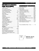
TABLE OF CONTENTS MQ Whiteman Modular Light T ower (ML T) Tower (MLT) Here's How To Get Help ............................................ 3 Table Of Contents ..................................................... 4 Parts Ordering Procedures ....................................... 5 Safety Message Alert Symbols .............................. 6-7 Rules For Safe Operation ...................................... 8-9 Operation and Safety Decals ............................. 10-11 Specifications ...................
www.multiquip.com Effective: June 1st, 2005 PARTS ORDERING PROCEDURES Ordering parts has never been easier! Choose from three easy options: Best Deal! Order via Internet (Dealers Only): If you have an MQ Account, to obtain a Username and Password, E-mail us at: parts@multiquip.com. Order parts on-line using Multiquip’s SmartEquip website! ■ View Parts Diagrams ■ Order Parts ■ Print Specification Information To obtain an MQ Account, contact your District Sales Manager for more information.
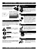
MODULAR LIGHT TOWER — SAFETY MESSAGE ALERT SYMBOLS FOR YOUR SAFETY AND THE SAFETY OF OTHERS! Safety precautions should be followed at all times when operating this equipment. Failure to read and understand the Safety Messages and Operating Instructions could result in injury to yourself and others. NOTE This Owner's Manual has been developed to provide complete instructions for the safe and efficient operation of the MQ Whiteman Modular Light Tower (MLT) .
MODULAR LIGHT TOWER — SAFETY MESSAGE ALERT SYMBOLS Accidental Starting Hazard QP-202TH — SAFETY Respiratory MESSAGE ALERT SYMBOLS ALWAYS place the power source, circuit breakers or ON/OFF switch in the OFF position, when the generator is not in use, unless connected to transfer switch. Sight and Hearing hazard ALWAYS wear approved eye and hearing protection. ALWAYS wear approved respiratory protection.
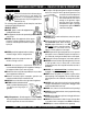
MODULAR LIGHT TOWER — RULES FOR SAFE OPERATION CAUTION: Failure to follow instructions in this manual may lead to serious injury or even death! This equipment is to be operated by trained and qualified personnel only! This equipment is for industrial use only. The following safety guidelines should always be used when operating the light tower/generator: GENERAL SAFETY ■ The engine of this light tower/generator requires an adequate free flow of cooling air.
MODULAR LIGHT TOWER — RULES FOR SAFE OPERATION DANGER DANGER: The 6 DANGER items listed below are considered high DANGER areas and should be adhered to. Failing to understand these areas could result in bodily harm electrical shock, electrocution, and even death! Please pay close attention when operating the light tower. DANGER To prevent serious injury or death, ALWAYS make sure area above trailer is open and clear of overhead powerlines andobstructions. The tower extends in excess of 30 ft.
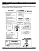
MODULAR LIGHT TOWER — OPERATION AND SAFETY DECALS Machine Safety Decals This modular light tower is equipped with a number of safety decals. These decals are provided for operator safety and maintenance information. The illustration below and on the next page shows these decals as they appear on the machine. Should any of these decals become unreadable, replacements can be obtained from your dealer. PAGE 10 — MODULAR LIGHT TOWER — PARTS & OPERATION MANUAL — REV.
MODULAR LIGHT TOWER — OPERATION AND SAFETY DECALS MODULAR LIGHT TOWER — PARTS & OPERATION MANUAL — REV.
MODULAR LIGHT TOWER — SPECIFICATIONS TABLE 1. SPECIFICATIONS Model MLT-DA7 Generator MLT-KD-6/KD1800Generator MLT-SDW Welder/Generator MLT (No Generator) Weight (Dry) 1,588 lbs. (720 kg.) 1,764 lbs. (800 kg.) 1768 lbs. (802 kg.) 1062 lbs. (481 kg.) L e n g th 173 in. (1,854 mm.) 173 in. (1,854 mm.) 173 in. (1,854 mm.) 173 in. (1,854 mm.) Height 70 in. (1,778 mm.) 70 in. (1,778 mm.) 70 in. (1,778 mm.) 70 in. (1,778 mm.) Width 50 in. (1,270 mm,) 50 in. (1,270 m.) 50 in. (1,270 m.
MODULAR LIGHT TOWER — GENERAL INFORMATION The Multiquip modular light tower is a general purpose floodlight tower intended for emergency and remote lighting conditions. This modular light tower (MLT) can be configured to operate with four different types of power sources: The DA-7000, KD-6, KD-1800 generators or the SDW-225SS welder/generator.
MODULAR LIGHT TOWER — DIMENSIONS Figure 1. Dimensions (Length and Width) PAGE 14 — MODULAR LIGHT TOWER — PARTS & OPERATION MANUAL — REV.
MODULAR LIGHT TOWER — DIMENSIONS Figure 2. Dimensions ( Maximum Mast Height) MODULAR LIGHT TOWER — PARTS & OPERATION MANUAL — REV.
MODULAR LIGHT TOWER — COMPONENTS Figure 3. Components Figure 3 shows the location of the controls and components for the Modular Light Tower. The functions of each control is described below: 1. Mast Rotation Locking Knob – Unscrew this knob to release mast for rotation. 2. Vertical Mast Extension Winch – Use this winch to extend the mast to the desire height. Maximum height is approximately 30 feet (9 meters). 3. Mast Rotation Handle – Grip this handle to rotate mast to desired position.
MODULAR LIGHT TOWER — FLOODLIGHT FOOTCANDLE PLOT Figure 4. Footcandle Plot Max Value = 59.00 MODULAR LIGHT TOWER — PARTS & OPERATION MANUAL — REV.
MODULAR LIGHT TOWER — FLOODLIGHT FOOTCANDLE PLOT Figure 5. Footcandle Plot Max Value = 24.11 PAGE 18 — MODULAR LIGHT TOWER — PARTS & OPERATION MANUAL — REV.
MODULAR LIGHT TOWER — FLOOD LIGHT FOOTCANDLE PLOT Figure 6. Footcandle Plot Max Value = 15.21 MODULAR LIGHT TOWER — PARTS & OPERATION MANUAL — REV.
MODULAR LIGHT TOWER — TOWING GUIDELINES Towing Safety Precautions CAUTION: ■ Check wheel mounting lug nuts with a torque wrench. Torque wheel lug nuts as described in the "Lug Nut Torque Requirements", Table 4 . ■ Check with your county or state safety towing regulations department before towing your light tower. ■ Make sure brakes are synchronized (electric only) and functioning properly.
MODULAR LIGHT TOWER — TOWING GUIDELINES Figure 7. Safety Chains/ Trailer Coupler Hook-up MODULAR LIGHT TOWER — PARTS & OPERATION MANUAL — REV.
MODULAR LIGHT TOWER — TRAILER SAFETY GUIDELINES Trailer Safety Precautions 4. Frame Length – This measurement is from the ball hitch to the rear bumper (reflector). 5. Frame Width – This measurement is from fender to fender. Jack Stand – Trailer support device with maximum pound requirement from the tongue of the trailer. Coupler – Type of hitch used on the trailer for towing. Tires Size – Indicates the diameter of the tire in inches (10, 12, 13, 14, etc.
MODULAR LIGHT TOWER — TRAILER SAFETY GUIDELINES Tab le 2. Trailer S p ecificatio n /Ap p licatio n MOD E L AP P L IC AT ION FU EL C ELL GAL L ON S B R AK E S YS T E M GV WR LB S. F R AM E L E N GT H IN C H E S F R AM E WID T H IN C H E S J AC K S TAN D C APAC IT Y (L B S ).
MODULAR LIGHT TOWER — TRAILER SAFETY GUIDELINES Tab le 2. S p ecificatio n s/Ap p licatio n (C o n 't) MOD E L C OU P L E R T IR E S R IMS AX L E HUBS S U S P E N S ION E L E C T R IC AL T R L R -1 0 -1 5 W 2" BALL CLASS 2 ADJUSTABLE 175-13C 13"X4.50" 2200 LBS. 2X2 5 LUG 3 LEAF 4 WIRE LOOM RUBBER FLAT T R L R -1 0 X 2"BALL CLASS 2 ADJUSTABLE 175-13C 13"X4.5" 2200 LBS. 2X2 5 LUG 3 LEAF 4 WIRE LOOM RUBBER FLAT T R L R -1 0 X F 2"BALL CLASS 2 ADJUSTABLE 175-13C 13"X4.5" 220 LBS.
MODULAR LIGHT TOWER — TRAILER SAFETY GUIDELINES Brakes If your trailer has a braking system, the brakes should be inspected the first 200 miles of operation. This will allow the brake shoes and drums to seat properly. After the first 200 mile interval, inspect the brakes every 3,000 miles. If driving over rough terrain inspect brakes more frequently. Electric Brakes Electrically actuated brakes (Figure 8) are similar to hydraulic brakes.
MODULAR LIGHT TOWER — TRAILER SAFETY GUIDELINES Figure 8. Electric Brake Components Hydraulic/Air/Surge Brakes Hydraulic brakes (Figure 9) should not require any special attention with the exception of routine maintenance such as shoe and lining replacement. These brakes can be adjusted in the same manner as electric brakes. Brake lines should be periodically checked for cracks, kinks, or blockage.
MODULAR LIGHT TOWER — TRAILER SAFETY GUIDELINES Tires/Wheels/Lug Nuts Tires and wheels are a very important and critical components of the trailer. When specifying or replacing the trailer wheels it is important the wheels, tires, and axle are properly matched. CAUTION: DO NOT attempt to repair or modify a wheel. DO NOT install an inter-tube to correct a leak through the rim.
MODULAR LIGHT TOWER — TRAILER SAFETY GUIDELINES Table 4. Suspension Torque Requirements Item Torque (Ft.-Lbs.) 3/8" U-BOLT MIN-30 MAX-35 7/16" U-BOLT MIN-45 MAX-60 1/2" U-BOLT MIN-45 MAX-50 SHACKLE BOLT SNUG FIT ONLY. PARTS MUST ROTATE FREELY. SPRING EYE BOLT LOCKING NUTS OR COTTER PINS ARE PROVIDED TO RETAIN NUT-BOLT ASSEMBLY. SHOULDER TYPE MIN-30 MAX-50 SHACKLE BOLT Lug Nut Torque Requirements It is extremely important to apply and maintain proper wheel mounting torque on the trailer.
MODULAR LIGHT TOWER — TRAILER WIRING DIAGRAM Figure 12. Typical Trailer Wiring Diagram MODULAR LIGHT TOWER — PARTS & OPERATION MANUAL — REV.
MODULAR LIGHT TOWER — TRAILER BRAKES (HYDRAULIC) TABLE 6. HYDRAULIC BRAKE TROUBLESHOOTING SYMPTON POSSIBLE CAUSE SOLUTION No brakes Is the brake line broken or kinked? Repair or replace. Is the brake lining glazed? Reburnish or replace Is the trailer overloaded? Correct weight. Are the brake drums scored or grooved? Machine or replace. Is the tire pressure correct? Inflate all tires equally per manufacturer guidelines. Are the tires unmatched on the same axle? Match tires.
MODULAR LIGHT TOWER — TRAILER BRAKES (ELECTRIC) TABLE 7. ELECTRIC BRAKE TROUBLESHOOTING SYMPTOM No brakes or intermittent brakes. POSSIBLE CAUSE SOLUTION Any open circuits or broken wires? Find and correct. Any shor t circuits? Find and correct. Faulty controller? Test and correct. Any loose connections? Find and repair. Is the ground wire secure? Find and secure. Is there grease or oil on the magnets or lining? Clean or replace.
MODULAR LIGHT TOWER — T-BAR INSTALLATION CAUTION: Indoor Installation Pay close attention to ventilation when operating the generator in enclosed areas. The engine exhaust contains noxious elements. Exhaust gases from gasoline engines are extremely poisonous. Whenever an engine is installed indoors the exhaust fumes must be vented to the outside. The engine should be installed at least two feet from any outside wall.
MODULAR LIGHT TOWER — TOWER MAST PRE-SETUP WARNING: ALWAYS check overhead for clearance of the mast. NEVER raise the mast in the vicinity of power lines! DO NOT stand behind the trailer while the mast is being raised or lowered. Outriggers and Support Stands 1. Make sure both outriggers are extended. To extend the outriggers, pull the locking pin on the outrigger and hold while sliding out the outrigger assembly. 2.
MODULAR LIGHT TOWER — ENGINE PRE-SETUP WARNING: Starting The engine's exhaust contains harmful emissions. ALWAYS ventilate the exhaust when operating inside tunnels, excavations or buildings. Direct exhaust away from nearby personnel. NEVER operate the light tower with the engine compartment doors open. Operation with the doors open may cause insufficient cooling to the unit, and damage may result. Before Starting 1.
MODULAR LIGHT TOWER — OPERATION Operation Proceed with this section only if the following have been completed: 3. Set circuit breaker CB-1 (page 41) on the ballast box to the ON position. 4. Wait a few minutes for the ballast to activate. Observe that flood lights #1 and #2 are ON. z Outriggers have been fully extended to prevent the trailer from tipping. 5. Set circuit breaker CB-2 on the ballast box to the ON position. z All tower mast sections have been raised to the desired height.
MODULAR LIGHT TOWER — MAINTENANCE Check Cable Wear The wire rope (cable) that raises and extends the mast is a very important part of the light tower. There is one cable that raises and extends the lower portion of the mast. There is a second cable that serves to extend the top portion of the mast. Wire rope (cable) will fail if it is worn, frayed, misused, crushed, kinked or damaged in any way. Always check the mast cable and pulleys for any abnormalities before use.
MODULAR LIGHT TOWER — PREPARATION FOR LONG -TERM STORAGE Generator Storage For storage of the generator for over 30 days, the following is required: z Drain the fuel tank completely. z Run the engine until all the fuel is completely consumed. z Completely drain the oil from the crankcase and refill with fresh oil. z Disconnect the negative battery cable from the battery. z Clean all external parts of the generator with a cloth. z Cover the generating set and store in a clean, dry place.
MODULAR LIGHT TOWER — TROUBLESHOOTING TABLE 8. MODULAR LIGHT TOWER TROUBLESHOOTING SYMPTOM POSSIBLE PROBLEM Lamp Burned Out? Test the lamp in a fixture which is operating properly. Replace as necessary. Lamp Loose in Socket? Inspect lamp base to see if there is arcing at center contact button. Tighten lamp snugly. Check socket for damage. Replace if defective. Floodling Plugs Not Tight? Check plug and receptacle. Tighten if loose. Defective Ballast? Interchange ballast plugs in generator enclosure.
MODULAR LIGHT TOWER — TROUBLESHOOTING TABLE 8. MODULAR LIGHT TOWER TROUBLESHOOTING (CONTINUED) SYMPTOM POSSIBLE PROBLEM SOLUTION Lamp star ts slowly (ARC does nt strike when switch is first turned on) Defective Lamp? Lamp may glow for extended period of time. Replace after checking voltage and ballast. Circuit breaker trips on lamp star t-up Shor t Circuit or Ground? Check wiring against diagram. Check for shor ts or ground. Normal Lamp Depreciation? Replace Lamp.
MODULAR LIGHT TOWER — TROUBLESHOOTING TROUBLESHOOTING GUIDE Use the following procedure to determine which of the four floodlights is not functioning: Connections: 1. Make sure that floodlight #1 power cable is plugged into the J1 connector on the T-Bar assembly. 2. Make sure that floodlight #2 power cable is plugged into the J2 connector on the T-Bar assembly. 3. Make sure that floodlight #3 power cable is plugged into the J3 connector on the T-Bar assembly. 4.
MODULAR LIGHT TOWER — SCHEMATIC DIAGRAM LIGHT TOWER SCHEMATIC DIAGRAM NOTE Capacitors C1 thru C4 are 480 VAC, 24μf. In addition a 47K Ω (1/2 watt) resistor is installed across the capacitor terminals. MODULAR LIGHT TOWER — PARTS & OPERATION MANUAL — REV.
MODULAR LIGHT TOWER — BALLAST COMPARTMENT WIRING DIAGRAM. BALLAST COMPARTMENT WIRING DIAGRAM PAGE 42 — MODULAR LIGHT TOWER — PARTS & OPERATION MANUAL — REV.
MODULAR LIGHT TOWER— ELECTRIC SWITCH WIRING DIAGRAM ELECTRIC FUEL SWITCH WIRING DIAGRAM. MODULAR LIGHT TOWER — PARTS & OPERATION MANUAL — REV.
EXPLANATION OF CODE IN REMARKS COLUMN How to read the marks and remarks used in this parts book. Items Found In the “Remarks” Column Serial Numbers-Where indicated, this indicates a serial number range (inclusive) where a particular part is used. Model Number-Where indicated, this shows that the corresponding part is utilized only with this specific model number or model number variant.
MODULAR LIGHT TOWER — SPARE PARTS MODULAR LIGHT TOWER 1 TO 3 UNITS Qty. P/N Description 2 ............ 64167441 .............. CLAMP, LIGHT 2 ............ 64167100 .............. GASKET, LENS 2 ............ 64167744 .............. LENS (GLASS) 2 ............ 19823 .................... SUPPORT, TOP LAMP 1000W 2 ............ M1000U ................ BULB 2 ............ C4403590 ............. REFLECTOR, REAR (OLD STYLE) 2 ............ 4105012 ................ REFLECTOR, -(NEW STYLE) 1 ............ 3805208 .....
MODULAR LIGHT TOWER — NAME PLATE AND DECALS NAME PLATE AND DECALS PAGE 46 — MODULAR LIGHT TOWER — PARTS & OPERATION MANUAL — REV.
MODULAR LIGHT TOWER — NAME PLATE AND DECALS NAME PLATE AND DECALS NO 1 * 2 * 3 * 4 * 5 * 6 * 7 * 8 * 9 * 10 * 11 * 12 * 13 PART NO B9504000304 19655 DCL111 13118 DCL109 DCL104 DCL117 DCL106 29157 DCL110 19021 DCL102 14 * 15 * 16 * 17 * 18 * 19 * 20 * 21 * 22 * 23 * 24 * 25 * 26 * 26 DCL113 DCL119 DCL112 DCL115 DCL105 DCL100 DCL120 DCL108 DCL116 DCL103 DCL118 29651 29425 DCLMLTKIT PART NAME QTY.
MODULAR LIGHT TOWER — MAST ASSEMBLY TOWER MAST ASSY. PAGE 48 — MODULAR LIGHT TOWER — PARTS & OPERATION MANUAL — REV.
MODULAR LIGHT TOWER — MAST ASSEMBLY TOWER MAST ASSY.
MODULAR LIGHT TOWER — WINCH ASSY. WINCH ASSY. PAGE 50 — MODULAR LIGHT TOWER — PARTS & OPERATION MANUAL — REV.
MODULAR LIGHT TOWER — WINCH ASSY. WINCH ASSY. NO PART NO PART NAME 1 2 3 4 5 6 7 8 9 10 11 12 13% 14 15 16 17# 18# 19# 20# 21# 22# 23 24% 25% 26% 27% 28 29 30 31 32 33 34 35 562101 CABLE KEEPER KIT ............................ 2 ........ INCLUDES ITEM W/ NUT 2 WASHER, LOCK 2 CABLE CLAMP 1 CARRIAGE BOLT 2 DRUM ASSY. ........................................ 1 ........ SEE NOTE 1 BELOW DRUM SPACER .................................... 1 ........ SEE NOTE 1 BELOW HANDLE ASSY. 1 LOCK NUT 1/2-13 .............
MODULAR LIGHT TOWER — FLOODLIGHT MOUNTING ASSY. FLOODLIGHT MOUNTING ASSY. PAGE 52 — MODULAR LIGHT TOWER — PARTS & OPERATION MANUAL — REV.
MODULAR LIGHT TOWER — FLOODLIGHT MOUNTING ASSY. FLOODLIGHT MOUNTING ASSY. NO PART NO PART NAME 1 2 3 4 5 6 7 8 9 10 11 12 13 14 15 16 17 18 19 20 21 22 19249 5079 29174 19940 19250 19956 11505 19955 10176 0447 3215 16786 29161 29162 29042 29169 19972 19945 19944 29046 19688 19687 SCREW, HHC 3/4-16 x 4 FLAT WASHER, 3/4 FLOOD LIGHT, ASSY. MOUNT, LIGHT FIXTURE W/A NUT, NYLOC 3/4-16 x 4 TOWER MASTS, ASSY. CLIP, CABLE LEAD ASSY.
MODULAR LIGHT TOWER — LIGHT FIXTURE ASSY. LIGHT FIXTURE ASSY. S/N 4GNLT1018YB900071 AND BELOW PAGE 54 — MODULAR LIGHT TOWER — PARTS & OPERATION MANUAL — REV.
MODULAR LIGHT TOWER — LIGHT FIXTURE ASSY. LIGHT FIXTURE ASSY.
MODULAR LIGHT TOWER — LIGHT FIXTURE ASSY. LIGHT FIXTURE ASSY. S/N 4GNLT1018YB900072 AND ABOVE PAGE 56 — MODULAR LIGHT TOWER — PARTS & OPERATION MANUAL — REV.
MODULAR LIGHT TOWER — LIGHT FIXTURE ASSY. LIGHT FIXTURE ASSY. S/N 4GNLT1018YB900072 AND ABOVE NO 1 * 2 * 3 * 4 * 5 * 6 * 7 * 8 * 9 * 10 * 11 * 12 * 13 * 14 * 15 * 17 * 18 * 19 * 20 * 21 * 22 * 23 * 24 * 25 * 26 * 27 * 28 * 29 * 30 * 31 * 32 PART NO 64167441 64167100 64167744 19823 M1000U 4101024 4105012 4605079000 70463 2450120 3100056 29169 4110624000 6900446 6900447 4101021 63960 29162 5232GR 4107742000 2856 19688 4100003 2450121 6351110 6301045 2450119 4106781000 4104021000 4101023 29174 PART NAME QTY.
MODULAR LIGHT TOWER — TRAILER ASSY. TRAILER ASSY. PAGE 58 — MODULAR LIGHT TOWER — PARTS & OPERATION MANUAL — REV.
MODULAR LIGHT TOWER — TRAILER ASSY. TRAILER ASSY. NO. 1 2 3 4 5 6 7 8 9 PART NO. 29020 29077 19989 9503 29158 10024 0730 0948 10 11 12 13 14 15 16 17 18 19 20 21 22 23 24 25 26 27 28 29 30 31 32 33 34 35 36 37 38 39 19904 19102 9502 9503 29095 29074 29212 19045 8115 9510 19525 9514 19948 16524 16630 16629 0205 3233 10136 10133 19527 29067 0131A 0181B 29101 29008 1135 10176 29017 29211 PART NAME QTY.
MODULAR LIGHT TOWER — AXLE ASSY. AXLE ASSY. PAGE 60 — MODULAR LIGHT TOWER — PARTS & OPERATION MANUAL — REV.
MODULAR LIGHT TOWER — AXLE ASSY. AXLE ASSY. NO. 1 2 3# 4# 5# 6# 7# 8# 9 * 10 11 # * 12# 13 PART NO. 8115 19045 568067 363277 363257 363258 363259 363180 363913 363188 363908 363275 29067 PART NAME QTY. REMARKS ° 10 NUT, LUG 1/2 - 20 60 CONE WHEEL & TIRE ASSY. 2 RUBBER PLUG (AG) 2 GREASE CAP (AG) 2 SPINDLE NUT 1"-1/4 2 COTTER PIN 2 WASHER, SPINDLE 2 BEARING CONE (INNER & OUTER) 4 BEARING CUP (INNER & OUTER) 4 HUB ASSY., IDLER ...................................... 2 ............
MODULAR LIGHT TOWER — FUEL TANK ASSY. FUEL TANK ASSY. PAGE 62 — MODULAR LIGHT TOWER — PARTS & OPERATION MANUAL — REV.
MODULAR LIGHT TOWER — FUEL TANK ASSY FUEL TANK ASSY. NO PART NO PART NAME 1 2 3 4 5 6 7 8 9 10 11 12008 60058 19633 12006 12008 19473 60028 60058 19094 19984 19983 SCREEN, FILTER HOSE.375 0D X .25 ID PVC FUEL YELLOW, 1.O FT BUSHING, RUBBER FUEL FITTING, 90 03BARB-4BARB FUEL FITTING, 90 FUEL CLAMP, WORM HOSE, #4 (1/4-5/8) HOSE, .312 ID RUBBER FUEL, 1.6 FT. LONG HOSE, .187 ID RUBBER, 2.25 FT. LONG LINER, FUEL TANK CAP, FUEL W/GAUGE (5-3/4) TANK, FUEL QTY.
MODULAR LIGHT TOWER — OPTIONAL ELECTRIC FUEL SWITCH ASSY. OPTIONAL ELECTRIC FUEL SWITCH ASSY. (FUEL TANK) PAGE 64 — MODULAR LIGHT TOWER — PARTS & OPERATION MANUAL — REV.
MODULAR LIGHT TOWER — OPTIONAL ELECTRIC FUEL SWITCH ASSY. OPTIONAL ELECTRIC FUEL SWITCH ASSY. (FUEL TANK) NO PART NO PART NAME 1 2 3 4 29164 19870 29165 19473 VALVE, SELECTOR-DC .............................................. 1 ..... OPTION CAP, VACUUM PLUG 2 CONNECTOR ASSY.-SWITCH 1 CLAMP, HOSE #4 7 QTY. REMARKS MODULAR LIGHT TOWER — PARTS & OPERATION MANUAL — REV.
MODULAR LIGHT TOWER — SUPPORT STANDS ASSY. SUPPORT STANDS ASSY. PAGE 66 — MODULAR LIGHT TOWER — PARTS & OPERATION MANUAL — REV.
MODULAR LIGHT TOWER — SUPPORT STANDS ASSY. SUPPORT STANDS ASSY. NO PART NO PART NAME 1 2 3 4 5 6 7 1284 10136 10133 19950 19997 19931 4022 SCREW, HHC 3/8-16 X 1-1/2 WASHER, FLAT 3/8 SAE NUT, NYLOC 3/8-16 PIN, LOCK REAR SUPPORT HANDLE, 5/8 X4 RED SUPPORT, REAR TOWER ROLL PIN 1/4 X 2 QTY. REMARKS 4 4 4 1 1 1 1 MODULAR LIGHT TOWER — PARTS & OPERATION MANUAL — REV.
MODULAR LIGHT TOWER — GEN/WELDER TRAILER MOUNTING ASSY. GENERATOR/WELDER TRAILER MOUNTING ASSY. PAGE 68 — MODULAR LIGHT TOWER — PARTS & OPERATION MANUAL — REV.
MODULAR LIGHT TOWER — GEN/WELDER TRAILER MOUNTING ASSY. GENERATOR/WELDER TRAILER MOUNTING ASSY. NO PART NO PART NAME 1 2 3 5218 0447 10176 SCREW, HHC 1/2-13 X1-1/2 WASHER, FLAT 1/2 SAE NUT, NYLOC 1/2-13 QTY. REMARKS 4 8 4 MODULAR LIGHT TOWER — PARTS & OPERATION MANUAL — REV.
MODULAR LIGHT TOWER — COIL CORD ASSY. COIL CORD ASSY. PAGE 70 — MODULAR LIGHT TOWER — PARTS & OPERATION MANUAL — REV.
MODULAR LIGHT TOWER — COIL CORD ASSY. COIL CORD ASSY. NO PART NO PART NAME 1 2 3 4 5 19798 10104 3254 11947 19955 COIL CORD 1 TERMINAL, SPADE 12-10, #10 INS 1 TERMINAL, RING 16-14 3/8 1 TERMINAL, FEM PUSH, 16-14 INSUL 4 COIL CORD ASSY. ............................................ 1 ............... INCLUDES ITEMS W/ * * * * QTY. REMARKS * MODULAR LIGHT TOWER — PARTS & OPERATION MANUAL — REV.
MODULAR LIGHT TOWER — POWER CABLE ASSY. POWER CABLE ASSY. PAGE 72 — MODULAR LIGHT TOWER — PARTS & OPERATION MANUAL — REV.
MODULAR LIGHT TOWER — POWER CABLE ASSY. POWER CABLE ASSY. NO PART NO PART NAME 1 2 3 4 5 19798 10105 29069 19686 29068 CABLE ELEC 10 AWG X 4 ................................ 1 ............... COND-600V TERMINAL, RING 12-10, #10 INS 3 TERMINAL, RING 10-12AWY X 3/8 IN 1 PLUG, LOCKING ............................................... 1 ............... P1 LEAD ASSEMBLY, POWER ............................... 1 ............... INCLUDES ITEMS W/ * * * QTY.
MODULAR LIGHT TOWER — BALLAST COMPARTMENT COVER ASSY. BALLAST COMPARTMENT COVER ASSY. PAGE 74 — MODULAR LIGHT TOWER — PARTS & OPERATION MANUAL — REV.
MODULAR LIGHT TOWER — BALLAST COMPARTMENT COVER ASSY. BALLAST COMPARTMENT COVER ASSY. GENERATOR/WELDER TRAILER MOUNTING ASSY. NO PART NO PART NAME 1 2 3 4 5 29000 29093 0202 0161C 0300B PLATE, COVER 1 GASKET ............................................................. 6 ............... QTY 6= 72 INCHES SCREW, HHC 5/16-18 X 1 4 WASHER, LOCK 5/16 4 WASHER, FLAT 5/16 4 QTY. REMARKS MODULAR LIGHT TOWER — PARTS & OPERATION MANUAL — REV.
MODULAR LIGHT TOWER — BALLAST COMPARTMENT ASSY. BALLAST COMPARTMENT ASSY. PAGE 76 — MODULAR LIGHT TOWER — PARTS & OPERATION MANUAL — REV.
MODULAR LIGHT TOWER — BALLAST COMPARTMENT ASSY. BALLAST COMPARTMENT ASSY. NO PART NO PART NAME 1 2 3 4 5 6 7 8 9 10 11 12 13 14 15 17 18 19 20 21 22 23 24 25 29156 10434 11152 1450 29098 29097 8133 29000 8133 10136 1JP104S 0166A 29001 19968 10019 10133 19999 19858 13252 29093 19598 10024 0131A 0948 BALLAST 1000W, MH CWA 120 VAC ........... 4 CLAMP, 2-INCH HOSE 4 NUT, NYLOC 6-32 4 WASHER, FLAT #6 SAE 12 FAN ASSY.
Effective: February 22, 2006 PAYMENT TERMS TERMS AND CONDITIONS OF SALE — PARTS 5. Parts must be in new and resalable condition, in the original Multiquip package (if any), and with Multiquip part numbers clearly marked. 6. The following items are not returnable: Terms of payment for parts are net 30 days. FREIGHT POLICY All parts orders will be shipped collect or prepaid with the charges added to the invoice. All shipments are F.O.B. point of origin.
NOTE PAGE MODULAR LIGHT TOWER — PARTS & OPERATION MANUAL — REV.
PARTS AND OPERATION MANUAL HERE'S HOW TO GET HELP PLEASE HAVE THE MODEL AND SERIAL NUMBER ON-HAND WHEN CALLING PARTS DEPARTMENT 800-427-1244 or 310-537-3700 FAX: 800-672-7877 or 310-637-3284 SERVICE DEPARTMENT/TECHNICAL ASSISTANCE 800-478-1244 or 310-537-3700 FAX: 310- 537-4259 WARRANTY DEPARTMENT 888-661-4279, or 310-661-4279 FAX: 310- 537-1173 MAIN 800-421-1244 or 310-537-3700 FAX: 310-537-3927 MULTIQUIP INC.