OPERATION MANUAL SERIES MODEL CA4HM WALK-BEHIND TROWEL KOHLER 27 HP (HONDA GX120K1QX2/GX120UT1QX2 KOHLER HP EFI GASOLINE28 ENGINE) Revision #3 (10/28/10) To find the latest revision of this publication, visit our website at: www.multiquip.com THIS MANUAL MUST ACCOMPANY THE EQUIPMENT AT ALL TIMES.
PROPOSITION 65 WARNING Engine exhaust and some of its constituents, and some dust created by power sanding, sawing, grinding, drillingandotherconstructionactivities contains chemicals known to the State of California to cause cancer, birth defects and other reproductive harm. Some examples of these chemicals are: Leadfromlead-basedpaints. Crystallinesilicafrombricks. Cementandothermasonryproducts. Arsenicandchromiumfromchemically treatedlumber.
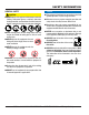
SILICOSIS/RESPIRATORY WARNINGS WARNING WARNING SILICOSIS WARNING RESPIRATORY HAZARDS Grinding/cutting/drilling of masonry, concrete, metal and other materials with silica in their composition may give off dust or mists containing crystalline silica. Silica is a basic component of sand, quartz, brick clay, granite and numerous other minerals and rocks. Repeated and/or substantial inhalation of airborne crystalline silica can cause serious or fatal respiratory diseases, including silicosis.
TABLE OF CONTENTS MQ WHITEMAN CA4HM WALK-BEHIND TROWEL Proposition 65 Warning ............................................. 2 Silicosis/Respiratory Warnings .................................. 3 Training Checklist ...................................................... 5 Daily Pre-Operation Checklist ................................... 6 Safety Information ................................................ 7-11 Dimensions ............................................................. 12 Specifications ..........
TRAINING CHECKLIST Training Checklist No. Description 1 Read Operator’s Manual completely. 2 Machine layout, location of components, checking of engine and hydraulic oil levels. 3 Fuel system, refueling procedure. 4 Operation of spray and lights. 5 Operation of controls (machine not running). 6 Safety controls, safety stop switch operation. 7 Emergency stop procedures. 8 Star tup of machine, pre-heat, engine choke. 9 Maintaining a hover. 10 Maneuvering. 11 Pitching.
DAILY PRE-OPERATION CHECKLIST Daily Pre-Operation Checklist 1 Engine oil level. 2 Hydraulic oil level. 3 Radiator coolant level. 4 Condition of blades. 5 Blade pitch operation. 6 Safety Stop Switch operation. 7 Steering control operation. PAGE 6 — CA4HM WALK-BEHIND TROWEL — OPERATION MANUAL — REV.
SAFETY INFORMATION Do not operate or service the equipment before reading the entire manual. Safety precautions should be followed at all times when operating this equipment. Failure to read and understand the safety messages and operating instructions could result in injury to yourself and others. Potential hazards associated with the operation of this equipment will be referenced with hazard symbols which may appear throughout this manual in conjunction with safety messages.
SAFETY INFORMATION GENERAL SAFETY CAUTION NEVER operate this equipment without proper protective clothing, shatterproof glasses, respiratory protection, hearing protection, steel-toed boots and other protective devices required by the job or city and state regulations. Avoid wearing jewelry or loose fitting clothes that may snag on the controls or moving parts as this can cause serious injury. NEVER operate this equipment when not feeling well due to fatigue, illness or when under medication.
SAFETY INFORMATION TROWEL SAFETY NOTICE ALWAYS keep the machine in proper running condition. DANGER Engine fuel exhaust gases contain poisonous carbon monoxide. This gas is colorless and odorless, and can cause death if inhaled. The engine of this equipment requires an adequate free flow of cooling air. NEVER operate this equipment in any enclosed or narrow area where free flow of the air is restricted.
SAFETY INFORMATION NOTICE NEVER run engine without an air filter or with a dirty air filter. Severe engine damage may occur. Service air filter frequently to prevent engine malfunction. NEVER tamper with the factory settings of the engine or engine governor. Damage to the engine or equipment can result if operating in speed ranges above the maximum allowable. Store fuel in appropriate containers, in well-ventilated areas and away from sparks and flames. NEVER use fuel as a cleaning agent.
SAFETY INFORMATION GENERATOR SAFETY If using a generator to power trowel, refer to applicable generator manual safety information section. ELECTRICAL SAFETY DANGER NEVER let power cords or cables lay in water. NEVER use damaged or worn cables or cords when connecting equipment to generator. Inspect for cuts in the insulation. NEVER grab or touch a live power cord or cable with wet hands. The possibility exists of electrical shock, electrocution or death.
DIMENSIONS D B A C Figure 1. CA4HM Trowel Dimensions Table 1. CA4HM Trowel Dimensions & Weight A-Height (Lifting Bale) 711 mm (28.0 in.) B - Height (Engagement Lever) 921 mm (36.25 in.) C - Width 610 mm (24 in.) D - Length 1.55 m (5.08 ft.) Weight 57 kg (125 lbs.) PAGE 12 — CA4HM WALK-BEHIND TROWEL — OPERATION MANUAL — REV.
SPECIFICATIONS Table 2. CA4HM Trowel Specifications Number of Blades 4 Ring Diameter 24.0 in. (61 cm.) Ro t o r 70-130 RPM Path Width 24 in. (61 cm.) Vibration (Hand/Arm)1 3.85 m/s2 Sound Pressure (A-Weighted)2 83.5 dB(A) Sound Pressure (Peak, C-Weighted) 90.5 dB(C) Sound Power Level (A-Weighted) NOTE: 1.
GENERAL INFORMATION Intended Use Spider Operate the CA4HM Trowel, tools and components in accordance with the manufacturer's instructions. Use of any other tools for stated operation is considered contrary to designated use. The risk of such use lies entirely with the user. The manufacturer cannot be held liable for damages as a result of misuse. The vertical output shaft of the gearbox connects to a cast hub called the spider.
COMPONENTS 1 3 Figure 2. Controls and Components 2 11 10 5 4 6 9 8 7 Figures 2 shows the location of the basic controls or components, for the CA4HM TROWEL. Listed below is a brief explanation of each control or component 1. 2. Quick Pitch™ Control Handle – To adjust the pitch of the blades, grasp the handle then squeeze and either move the handle forward or backward to achieve the desired blade pitch. Throttle Control Lever – Controls the speed of the engine.
BASIC ENGINE Figure 3. Honda GX120K1QX2/UT1QX2 Engine Controls and Components INITIAL SERVICING The engine (Figure 3) must be checked for proper lubrication and filled with fuel prior to operation. Refer to the manufacturer's engine manual for instructions & details of operation and servicing. The engine shown above is a HONDA engine, operation for other types of engines may vary somewhat. 1. Fuel Filler Cap – Remove this cap to add unleaded gasoline to the fuel tank. Make sure cap is tightened securely.
ASSEMBLY Quick Pitch™ Handle Assembly Unfolding the Trowel for Operation The CA4HM TROWEL is equipped with a folding upper handle (Figure 4). It was assembled at the factory and shipped in its folded or stow position. You will need to unfold and adjust the trowel handle to the upright position prior to operation. 1. NOTICE Considerable force may be required when moving the Quick Pitch™ handle forward or backward.
INSPECTION CAUTION ALWAYS wear approved eye and hearing protection before operating the trowel. NEVER place hands or feet inside the guard rings while the engine is running. ALWAYS shut the engine down before performing any kind of maintenance service on the trowel. Figure 5. Engine Oil Dipstick (Removal) 3. Insert and remove the dipstick without screwing it into the filler neck. Check the oil level shown on the dipstick. Before Starting 1. Read safety instructions at the beginning of manual. 2.
INSPECTION CAUTION DANGER EXPLOSIVE FUEL! Motor fuels are highly flammable and can be dangerous if mishandled. DO NOT smoke while refueling. DO NOT attempt to refuel the trowel if the engine is hot! or running. Disconnect the spark plug wire from the spark plug and secure away from the engine before performing maintenance or adjustments on the machine. V-Belt Check A worn or damaged V-belt can adversely affect the performance of the trowel.
OPERATION This section is intended to assist the operator with the initial start-up of the walk-behind trowel. It is extremely important that this section be read carefully before attempting to use the trowel in the field. DO NOT use your trowel until this section is thoroughly understood Figure 9. Throttle Lever (Idle Position) Lifting the Trowel Onto a Slab Extra care should be taken when lifting the trowel off the ground.
OPERATION 6. Grasp the starter grip (Figure 13) and slowly pull it out. The resistance becomes the hardest at a certain position, corresponding to the compression point. Pull the starter grip briskly and smoothly for starting. 2. After the engine cools, turn the engine start/stop switch to the “OFF” position (Figure 15). Figure 15. Engine ON/OFF Switch (OFF Position) Figure 13. Starter Grip 7. If the engine has started, slowly return the choke lever (Figure 11) to the OPEN position.
OPERATION The following steps are intended as a basic guide to machine operation, and are not to be considered a complete guide to concrete finishing. We suggest that all operators (experienced and novice) read “Slabs on Grade” published by the American Concrete Institute, Detroit, Michigan. Read the “Training” section of this manual for more information. 2. To maneuver the trowel, gently lift up on or press down on the main trowel handle.
OPERATION Figure 19 below illustrates a typical walk-behind trowel application. Practice maneuvering the trowel. The trick is to let the trowel do the work. Continue to practice maneuvering the trowel. Try to practice as if you were finishing a slab of concrete. Practice edging and covering a large area. Remember a good finishing technique is to work backwards. Be careful when moving backwards so that hazards can be avoided. The best way to get accustomed to the trowel is repeated use. Figure 19.
OPTIONS Optional Float Discs (Pans) Blades NOTICE Blades should be changed when they fail to finish concrete in a satisfactory manner. These round discs (Figure 21) attach to the spiders and allow the machine to “float ” on “wet ” concrete.The disc design allows early floating and easy movement from wet to dry areas.They are also very effective in embedding large aggregates and surface hardeners. Blades are a vital part of finishing concrete.
MAINTENANCE Trowel Arm Adjustment Procedure NOTICE See the engine manual supplied with your machine for appropriate engine maintenance schedule and troubleshooting guide for problems. At the front of the book there is a “Daily Pre-Operation Checklist ”. Make copies of this checklist and use it on a daily basis. CAUTION ALWAYS allow the engine to cool before servicing. NEVER attempt any maintenance work on a hot engine.
MAINTENANCE 2. Start engine, and bring trowel blades up to full speed and look for the following conditions: ■ Does the trowel have a perceived rolling or bouncing motion when in use? ■ Look at the trowel while it is running, does the guard ring “rock up and down” relative to the ground? b. Lift the upper trowel assembly off the spider assembly. A slight tap with a rubber mallet may be necessary to dislodge the spider from the main shaft of the gearbox. Trowel Arm Removal 1.
MAINTENANCE Checking Trowel Arm Straightness Trowel arms can be damaged by rough handling, (such as dropping the trowel on the pad), or by striking exposed plumbing, forms, or rebar while in operation. A bent trowel arm will not allow the trowel to operate in a smooth fluid rotation. If bent trowel arms are suspect, check for flatness as follows, refer to Figures 27 and 28: 3.
MAINTENANCE 4. Use an allen wrench to tighten the locking bolts securing the trowel arm in place. 5. Adjust the bolt "distance" shown in Figure 29 to match one of the arms. For a CA4HM trowel arm, this distance will be approximately 5/16" (7.938mm). The other arms will be adjusted to match this distance. 6. Loosen the locking nut on the trowel arm lever, then turn the trowel arm adjusting bolt until it barely touches (.010") the fixture adjusting bolt. 7.
MAINTENANCE Changing a Blade We recommend that all the blades be changed at the same time. The machine may wobble or bounce if only some of the blades are changed at one time. 1. Place the machine on a flat, level surface. Adjust the blade pitch control to make the blades as flat as possible. Note the blade orientation on the trowel arm. NOTICE Check the manual clutch occasionally for proper operation.
MAINTENANCE 1. Lift trowel just enough to slide pan under blades. Lower finisher onto pan with blades (item #1) adjacent to Z-Clips (item #4). Installing Pans Onto Finisher Blades 2. Rotate blades into position under Z-Clips. Ensure that the blades are rotated in the direction of travel when the machine is in operation or use the engine to rotate the blades into position. 3.
TROUBLESHOOTING Troubleshooting (Walk-Behind Trowel) Symptom Possible Problem Solution Engine ON/OFF Switch in "OFF" position Make sure that the Engine ON/OFF Switch is ON or malfunctioning? or replace switch if necessary. Engine running rough or not at all. Centrifugal stop switch malfunction? (if applicable) Make sure that the centrifugal stop switch is functioning when the operator is seated. Replace switch if necessary. Fuel? Look at the fuel system.
TROUBLESHOOTING Troubleshooting (Walk-Behind Trowel) - continued Symptom Machine has a perceptible rolling motion while running. Clutch slipping or sluggish response to engine speed change. Possible Problem Solution Main shaft? The main output shaft of the gearbox assembly should be checked for straightness. The main shaft must run straight and cannot be more than 0.003"" (0.08 mm) out of round at the spider attachment point.
TROUBLESHOOTING Troubleshooting (Engine) Symptom Possible Problem Solution Spark plug bridging? Check gap, insulation or replace spark plug. Carbon deposit on spark plug? Clean or replace spark plug. Short circuit due to deficient spark plug insulation? Check spark plug insulation, replace if worn. Improper spark plug gap? Set to proper gap. Fuel reaching carburetor? Check fuel line. Water in fuel tank? Flush or replace fuel tank. Fuel filter clogged? Replace fuel filter.
TROUBLESHOOTING Troubleshooting (Engine) - continued Symptom Weak in power, compression is proper and does not misfire. Weak in power, compression is proper but misfires. Engine overheats. Rotational speed fluctuates. Recoil starter malfunctions. (if applicable) Starter malfunctions. Possible Problem Air cleaner dirty? Clean or replace air cleaner. Improper level in carburetor? Check float adjustment, rebuild carburetor. Defective spark plug? Clean or replace spark plug.
ENGINE WIRING DIAGRAM YEL YEL OIL LEVEL SWITCH BLK BLK BLK OIL ALERT UNIT BLK ENGINE STOP SWITCH UNIT IGNITION COIL GRN TRANSISTORIZED IGNITION UNIT OIL LEVEL INDICATOR CHASSIS GND. CA4HM WALK-BEHIND TROWEL — OPERATION MANUAL — REV.
OPERATION MANUAL HERE’S HOW TO GET HELP PLEASE HAVE THE MODEL AND SERIAL NUMBER ON-HAND WHEN CALLING UNITED STATES Multiquip Corporate Office 18910 Wilmington Ave. Carson, CA 90746 Contact: mq@multiquip.com MQ Parts Department Tel. (800) 421-1244 Fax (800) 537-3927 Mayco Parts 800-427-1244 310-537-3700 Fax: 800-672-7877 Fax: 310-637-3284 Warranty Department 800-306-2926 310-537-3700 Fax: 800-672-7877 Fax: 310-637-3284 Service Department 800-421-1244, Ext. 279 310-537-3700, Ext.