OPERATION AND PARTS MANUAL SERIES MODEL MT54F TAMPING RAMMER (ROBIN EH09 GASOLINE ENGINE) Revision #8 (01/10/12) To find the latest revision of this publication, visit our website at: www.multiquip.com THIS MANUAL MUST ACCOMPANY THE EQUIPMENT AT ALL TIMES.
PROPOSITION 65 WARNING PAGE 2 — MT54F RAMMER — OPERATION AND PARTS MANUAL — REV.
NOTES MT54F RAMMER — OPERATION AND PARTS MANUAL — REV.
TABLE OF CONTENTS MIKASA MT54F Tamping Rammer Proposition 65 Warning ......................................... 2 Table Of Contents ................................................. 4 Parts Ordering Procedures ................................... 5 Safety Information ..............................................6-9 General Information ............................................ 10 Specification ........................................................ 11 Components...........................................
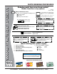
www.multiquip.com PARTS ORDERING PROCEDURES Ordering parts has never been easier! Choose from three easy options: Order via Internet (Dealers Only): Best Deal! Effective: January 1st, 2006 If you have an MQ Account, to obtain a Username and Password, E-mail us at: parts@multiquip. com. Order parts on-line using Multiquip’s SmartEquip website! ■ View Parts Diagrams ■ Order Parts ■ Print Specification Information To obtain an MQ Account, contact your District Sales Manager for more information.
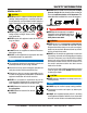
SAFETY INFORMATION Do not operate or service the equipment before reading the entire manual. Safety precautions should be followed at all times when operating this equipment. Failure to read and understand the safety messages and operating instructions could result in injury to yourself and others. Potential hazards associated with the operation of this equipment will be referenced with hazard symbols which may appear throughout this manual in conjunction with safety messages.
SAFETY INFORMATION GENERAL SAFETY CAUTION NEVER operate this equipment without proper protective clothing, shatterproof glasses, respiratory protection, hearing protection, steel-toed boots and other protective devices required by the job or city and state regulations. ALWAYS know the location of the nearest phone or keep a phone on the job site. Also, know the phone numbers of the nearest ambulance, doctor and fire department. This information will be invaluable in the case of an emergency.
SAFETY INFORMATION ENGINE SAFETY DANGER The engine fuel exhaust gases contain poisonous carbon monoxide. This gas is colorless and odorless, and can cause death if inhaled. FUEL SAFETY DANGER DO NOT add fuel to equipment if it is placed inside truck bed with plastic liner. Possibility exists of explosion or fire due to static electricity. The engine of this equipment requires an adequate free flow of cooling air.
SAFETY INFORMATION TRANSPORTING SAFETY CAUTION NEVER allow any person or animal to stand underneath the equipment while lifting. NOTICE Before lifting, make sure that the equipment parts (hook and vibration insulator) are not damaged and screws are not loose or missing. Always make sure crane or lifting device has been properly secured to the lifting bail (hook) of the equipment. ALWAYS shutdown engine before transporting. NEVER lift the equipment while the engine is running.
GENERAL INFORMATION Definition of Tamping Rammer The Mikasa MT-54F tamping rammer is a powerful compacting tool capable of applying a tremendous force in consecutive impacts to a soil surface. Its applications include soil compacting for road, embankments and reservoirs as well as backfilling for gas pipelines, water pipelines and cable installation work. The impact force of the MT-54F levels and uniformly compacts voids between soil particles to increase dry density.
SPECIFICATIONS Table1. MT-54F Rammer Specifications MODEL MT-54F U.S. (metric) Overall Height 40.5 in. (1,025 mm) Overall Width 14.6 in (370 mm) Over Length 26.4 in (670 mm) Shoe Size 10.4 x 13.4 in. (265 x 340 mm) Blows/minute 690 Impact Force 2,250 lbs./blow (1,110 kg/blow) Clutch Automatic Centrifugal Operating Weight 126 lbs. (57 kg) Table 2. Robin EH-09 STD Engine Specifications MODEL ROBIN EH-09 STD ENGINE Type Air-Cooled 4 Stroke Gasoline Engine Piston Displacement 5.20 cu.in.
MT-54F — CONTROLS ANDCOMPONENTS COMPONENTS Figure 1. MT-54F Tamping Rammer Figure 1 shows the location of the controls and components for the MT-54F Tamping Rammer. The functions of each control is described below: 1. Throttle Lever – Controls engine speed and the tamping action of the rammer. 2. Engine Stop Switch – Controls the starting and stopping of the engine. Switch must be in the "ON" position when starting the engine. 3. Choke Lever – Used when starting the engine.
BASIC ENGINE Figure 1-A. Engine Controls and Components INITIAL SERVICING The engine (Figure 1-A) must be checked for proper lubrication and filled with fuel prior to operation. Refer to the manufacturer's Engine manual for instructions and details of operation and servicing. 5. Recoil Starter (pull rope) – Manual-starting method. Pull the starter grip until resistance is felt, then pull briskly and smoothly. 1. Secondary Air Cleaner – Prevents dirt and other debris from entering the fuel system.
OPERATION This section is intended to assist the operator with the initial start-up of the MT-54F Tamping Rammer. It extremely important that this section be read carefully before attempting to operate the rammer. Engine 1. Fill the fuel tank (Figure 3 ) with unleaded gasoline. At the same time, check the engine oil and make it a habit to replenish it often. DO NOT use your rammer until this section is thoroughly understood.
OPERATION Inspection 1 . Check all nuts, bolts fasteners for tightness. Retighten as necessary. 2. Clean any dirt from the recoil starter and foot pedestal. Wipe the entire unit clean before operating. 3. Close the choke lever (Figure 7) . Turning the choke lever 90 degrees clockwise closes the choke . In cold weather, start the unit with choke fully closed. In warm weather or when the engine is warm, the unit can be started with choke halfway or completely open. 3.
OPERATION 6. When the engine starts, move the choke lever slowly to the "FULL OPEN" position. Warm up the engine by running at low speed for three to five minutes, check for gas leakage or abnormal sounds. 7. If the engine does not start after repeated attempts, check the spark plug for excess fuel. Clean and replace the spark plug as needed, then move the choke lever (Figure 7) to the half open position to avoid flooding and repeat steps 1 thru 5. 3.
MAINTENANCE Maintenance Perform the scheduled maintenance procedures as indicated: DAILY ■ Thoroughly remove dirt and oil from the engine and control area. Clean or replace the air cleaner elements as necessary. Check and retighten all fasteners as necessary. Check the spring box and bellows for oil leaks. Repair or replace as needed.
TROUBLESHOOTING MT-54F — TROUBLESHOOTING GUIDE TABLE 4. ENGINE TROUBLESHOOTING SYMPTOM POSSIBLE PROBLEM SOLUTION Difficult to start Fuel is available but spark plug will not ignite. (Power available at high tension cable). Fuel is available but spark plug will not ignite. (Power NOT available at high tension cable). Fuel is available and spark plug ignites (compression normal). Fuel is available and spark plug ignites (compression low ). Ignition plug being bridge? Check ignition system.
MT-54F — TROUBLESHOOTING TROUBLESHOOTING GUIDE ENGINE TABLE 4. ENGINE TROUBLESHOOTING (continued) SYMPTOM POSSIBLE PROBLEM SOLUTION Operation not satisfactory Rotational speed fluctuates. Recoil star ter not working properly. Governor adjustment improper? Adjust governor to correct lever. Governor spring defective? Clean or replace ignition. Fuel flow erratic? Check fuel line. Air taken in through suction line? Check suction line. Dust in rotating par t? Clean recoil star ter assembly.
EXPLANATION OF CODES IN THE REMARKS COLUMN The following section explains the different symbols and remarks used in the Parts section of this manual. Use the help numbers found on the back page of the manual if there are any questions. NOTICE The contents and part numbers listed in the parts section are subject to change without notice. Multiquip does not guarantee the availability of the parts listed. SAMPLE PARTS LIST NO. 1 2% 2% 3 4 PART NO. PART NAME QTY. REMARKS 12345 BOLT......................1 ....
SUGGESTED SPARE PARTS MT-54F RAMMER 1 TO 3 UNITS MT-54F RAMMER 5 TO 10 UNITS Qty. P/N Description 1 ............ 956225020 ............ LEVER, THROTTLE 3 ............ 354030030 ............ ELEMENT, YELLOW 3 ............ 354030040 ............ ELEMENT, GRAY 1 ............ 361910020 ............ CAP, FUEL TANK W/ STRAP 1 ............ 954405990 ............ COCK, FUEL ASSY. 1 ............ 954404890 ............ FILTER, FUEL TANK 2 ............ 301419750 ............ FILTER, IN-LINE FUEL 3 ............
NAMEPLATE AND DECALS 12 1 13 To start, switch must be in the “ON” position 14 2 NPA 293 3400 ~ 3600 RPM NPA 90 3 NPA-333 11 Mikasa CAUTION 4 10 READ 0WNER’S MANUAL NPA 629 5 Mikasa MT-54F 9 NAMEPLATE 6 7 8 PAGE 22 — MT54F RAMMER — OPERATION AND PARTS MANUAL — REV.
NAMEPLATE AND DECALS NO 1 2 3 4 5 6 7 8 9 10 11 12 13 14 * * * * * * * * * * * * * PART NO 920202930 920200900 920106460 920206290 1073273308 0732004430 0732004450 920203290 920107000 920204370 920206240 920203330 920203990 DCLMT54F PART NAME QTY. REMARKS DECAL: START SWITCH 1 NPA-293 DECAL: 3400 ~ 3600 RPM 1 NPA-90 DECAL: MIKASA 1 DECAL: READ OWNER'S MANUAL 1 NPA-629 DECAL: NOTICE 1 NPA-831 DECAL: START SWITCH 1 DECAL: WARNING 1 DECAL: CAUTION 1 NPA-329 PLATE, SERIAL NO. ................................
CRANKCASE AND ENGINE ASSY. PAGE 24 — MT54F RAMMER — OPERATION AND PARTS MANUAL — REV.
CRANKCASE AND ENGINE ASSY. NO PART NO PART NAME QTY. REMARKS 1 351109060 CRANKCASE 1 2 351324110 CRANK GEAR 1 CLUTCH GUIDEBEARING /A 1 3 040006305 6305 1 445 040006203 BEARING 6203 1 0053204201 WOODRUFF KEY 1 5 952401450 WASHER 8.5X22X3 1 46 301010210BOLTLOCK WASHER CLUTCH 1 6 011208025 8X25 T ........................................ 1 ............
CRANKCASE AND ENGINE MT-54F — CRANKCASE AND ENGINE ASSY. ASSY. PAGE 26 — MT54F RAMMER — OPERATION AND PARTS MANUAL — REV.
CRANKCASE AND ENGINE MT-54F — CRANKCASE AND ENGINE ASSY. ASSY.
GUIDE CYLINDER AND FOOT ASSY. 100 PAGE 28 — MT54F RAMMER — OPERATION AND PARTS MANUAL — REV.
GUIDE CYLINDER AND FOOT ASSY.
MT-54FTANK — TANK AND ANDHANDLE HANDLE ASSY. ASSY. PAGE 30 — MT54F RAMMER — OPERATION AND PARTS MANUAL — REV.
AND HANDLE MT-54FTANK — TANK AND HANDLE ASSY. ASSY. NO PART NO PART NAME A 1 2-1# 2-2# 3 5% 6% 6-1 % 7% 8% 9% 10 ♦ 10-1♦ ♦ 10-2♦ ♦ 10-3♦ 11% 13 14 15 16 17 21 46 47 48 49 61 62 63 64 305910030 351337070 001521020 033121009 012210020 305112820 361910020 353449010 954404890 351437785 954406020 954405990 0642001410 0642001420 0642001430 954406010 011208030 030208200 022710809 952401450 954404590 362116050 351436350 351435160 301419750 301420730 361910040 091005025 031105080 022610505 FUEL TANK ASSY.,2L ..
ROBIN EH09 ENGINE —— CRANKCASE ROBIN EH-09 ENGINE CRANKCASE ASSY. ASSY. PAGE 32 — MT54F RAMMER — OPERATION AND PARTS MANUAL — REV.
ROBIN EH09 ENGINE —— CRANKCASE ROBIN EH-09 ENGINE CRANKCASE ASSY. ASSY.
ROBIN EH09 ENGINE — CRANKSHAFT AND PISTON ASSY. PAGE 34 — MT54F RAMMER — OPERATION AND PARTS MANUAL — REV.
ROBIN EH09 ENGINE — CRANKSHAFT AND PISTON ASSY. NO PART NO PART NAME 10 40 2742010131 0230200100 0230200110 0230200120 0021812000 030212300 0053203101 0053204201 0173120010 2302250120 2302300123 2302330103 2742340103 2742340203 2742340303 2742350107 2742350207 2742350307 0565110010 CRANKSHAFT CP 1 SPACER T=0.8 1 SPACER T=1.0 1 SPACER T=1.2 1 NUT 1 SPRING WASHER .................................. 1 ..........REPLACES 0032012000 WOODRUFF KEY 1 WOODRUFF KEY 1 LOCK NUT 1 CONNECTING ROD ASSY. ..............
ROBIN EH09 ENGINE — INTAKE AND EXHAUST ASSY. PAGE 36 — MT54F RAMMER — OPERATION AND PARTS MANUAL — REV.
ROBIN EH09 ENGINE — INTAKE AND EXHAUST ASSY.
ROBIN EH09 ENGINE — GOVERNOR ASSY. PAGE 38 — MT54F RAMMER — OPERATION AND PARTS MANUAL — REV.
ROBIN EH09 ENGINE — GOVERNOR ASSY. NO PART NO PART NAME 10 20 30 40 50 60 70 80 200 210 230 235 280 345 360 370 385 386 480 486 2744230103 2304220103 2744270103 1064280113 0031305000 0011406250 0186060020 2744250103 2304330210 0043104140 0140040070 2054600323 2264310301 0217100020 0043106300 020106050 2744510101 0110060050 2264500313 0230100040 GOVERNOR LEVER 1 GOVERNOR SHAFT 1 GOVERNOR ROD 1 ROD SPRING 1 CLIP 2 BOLT AND WASHER ASSY. 1 NUT 1 GOVERNOR SPRING 1 SPEED CONTROL ASSY.
ROBIN EH09 ENGINE — RECOIL STARTER ASSY. PAGE 40 — MT54F RAMMER — OPERATION AND PARTS MANUAL — REV.
ROBIN EH09 ENGINE — RECOIL STARTER ASSY. NO PART NO PART NAME 10 11 12 13 14 15 16 20 40 41 46 60 210 210-1 210-2 210-3 210-4 210-5 210-6 210-11 210-35 210-49 216 220 2745120211 2745510121 2745520101 0110060020 0011606140 2745500101 0110060050 2749170103 0110060050 0110060020 0110060020 2745260103 2745020100 2745011508 2745012008 2745011008 2615010008 2705012508 2275013108 2745014508 2705026108 2275015208 2069170103 0110060020 BLOWER HOUSING CP 1 BLOWER H. BKT. 1 CP 1 BLOWER H. BKT.
ROBIN EH09 ENGINE — CARBURETOR ASSY. PAGE 42 — MT54F RAMMER — OPERATION AND PARTS MANUAL — REV.
ROBIN EH09 ENGINE — CARBURETOR ASSY. NO PART NO PART NAME 210 -1 -3 -4 -5 -8 -11 -12 -14 -15 -16 -17 -18 -19 -22 -24 -26 -28 -29 -33 -40 -41 -101 -117 -123 2746230100 2746253508 2306252508 2376245108 2346242108 2746252008 2746253008 2246254308 2268250208 2146251508 2306255308 2078234508 2306254008 2306250608 2746240008 2266270118 2746235108 2246245008 2106231808 2306258108 1066239308 2066244608 2306258208 2746235008 2276240408 CARBURETOR ASSY. ......................... 1 ..........
ROBIN EH09 ENGINE — ELECTRIC DEVICE ASSY. PAGE 44 — MT54F RAMMER — OPERATION AND PARTS MANUAL — REV.
ROBIN EH09 ENGINE — ELECTRIC DEVICE ASSY. NO PART NO PART NAME 10 11 30 60 70 75 95 100 110 2307020831 2747020101 0011706250 0660000361 0150040090 0566030010 0659000010 0650140460 2307510113 FLYWHEEL CP IGNITION COIL CP BOLT & WASHER ASSY. SWITCH ASSY. TAPPING SCREW CLAMP PLUG TERMINAL SPARK PLUG, NGK BM6A SPARK PLUG CAP QTY. REMARKS 1 1 2 1 2 1 1 1 1 MT54F RAMMER — OPERATION AND PARTS MANUAL — REV.
TERMS AND CONDITIONS OF SALE — PARTS PAYMENT TERMS 5. Parts must be in new and resalable condition, in the original Multiquip package (if any), and with Multiquip part numbers clearly marked. 6. The following items are not returnable: Multiquip reserves the right to quote and sell direct to Government agencies, and to Original Equipment Manufacturer accounts who use our products as integral parts of their own products. a. SPECIAL EXPEDITING SERVICE Terms of payment for parts are net 30 days.
NOTES MT54F RAMMER — OPERATION AND PARTS MANUAL — REV.
OPERATION AND PARTS MANUAL HERE’S HOW TO GET HELP PLEASE HAVE THE MODEL AND SERIAL NUMBER ON-HAND WHEN CALLING UNITED STATES Multiquip Corporate Office 18910 Wilmington Ave. Carson, CA 90746 Contact: mq@multiquip.com MQ Parts Department Tel.