PARTS AND OPERATION MANUAL © COPYRIGHT 2004, MULTIQUIP INC. MULTIQUIP Model GLW-180H D.C. WELDER A.C. GENERATOR Revision #5 (03/14/05) MULTIQUIP INC.. PARTS DEPARTMENT: 18910 WILMINGTON AVE. 800-427-1244 CARSON, CALIFORNIA 90746 FAX: 800-672-7877 SERVICE DEPARTMENT/TECHNICAL ASSISTANCE: 310-537-3700 800-421-1244 800-478-1244 FAX: 310-537-3927 FAX: 310-631-5032 E-mail:mq@multiquip.com • www:multiquip.
WARNING CALIFORNIA Proposition 65 Warning This product contains or produces chemicals known to the State of California to cause cancer and birth defects (or other reproductive harm). DCL160 PAGE 2 — GLW-180H A.C. GENERATOR/WELDER — PARTS & OPERATION MANUAL — REV.
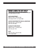
HERE'S HOW TO GET HELP PLEASE HAVE THE MODEL AND SERIAL NUMBER ON-HAND WHEN CALLING PARTS DEPARTMENT 800-427-1244 or 310-537-3700 FAX: 800-672-7877 or 310-637-3284 SERVICE DEPARTMENT/TECHNICAL ASSISTANCE 800-478-1244 or 310-537-3700 FAX: 310- 537-4259 WARRANTY DEPARTMENT 888-661-4279, or 310-661-4279 FAX: 310- 537-1173 MAIN 800-421-1244 or 310-537-3700 FAX: 310-537-3927 GLW-180H A.C. GENERATOR/WELDER — PARTS & OPERATION MANUAL — REV.
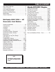
TABLE OF CONTENTS Here's How To Get Help ............................................ 3 Table Of Contents ..................................................... 4 Parts Ordering Procedures ....................................... 5 Rules For Safe Operation ......................................... 6 Operation and Safety Decals .................................... 7 Specifications ............................................................ 8 General Information ................................................
PARTS ORDERING PROCEDURES ■ ■ ■ ■ ■ ■ ■ Dealer account number Dealer name and address Shipping address (if different than billing address) Return fax number Applicable model number Quantity, part number and description of each part Specify preferred method of shipment: • • • • UPS Ground UPS Second Day or Third Day* UPS Next Day* Federal Express Priority One (please provide us with your Federal Express account number)* • • Airborne Express* Truck or parcel post *Normally shipped the same day the order
RULES FOR SAFE OPERATION CAUTION: Failure to follow instructions in this manual may lead to serious injury or even death! This equipment is to be operated by trained and qualified personnel only! This equipment is for industrial use only. The following safety guidelines should always be used when operating the GLW-180H Generator/Welder: GENERAL SAFETY ■ DO NOT operate or service this equipment before reading this entire manual. ■ This equipment should not be operated by persons under 18 years of age.
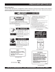
OPERATION AND SAFETY DECALS Machine Safety Decals The GLW-180H portable generator is equipped with a number of safety decals. These decals are provided for operator safety and maintenance information. The illustration below shows these decals as they appear on the machine. Should any of these decals become unreadable, replacements can be obtained from your dealer. GLW-180H A.C. GENERATOR/WELDER — PARTS & OPERATION MANUAL — REV.
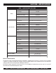
GLW-180H — SPECIFICATIONS Table 1. Specifications GLW-180H Max. Current 180 Amps Rated Voltage 26.4 Volts Duty Cycle 50% Welder Adjustable Current Range Rated Current Applicable Electrode Size Type Alternator 60 Cycle Generator 2-pole, Brushless Type Revolving Field Rated Output (continuous) 4000 Watts Rated Voltage 120 VAC Rated Current 33.
GLW-180H — GENERAL INFORMATION WARNING: Before connecting this generator to any building’s electrical system, a licensed electrician must install an isolation (transfer) switch. Serious injury or death may result without this transfer switch.
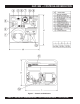
GLW-180H — CONTROLS AND INDICATORS Figure 1. Controls and Indicators PAGE 10 — GLW-180H A.C. GENERATOR/WELDER — PARTS & OPERATION MANUAL — REV.
GLW-180H — INSTRUMENTATION CAUTION : When using a combination of dual receptacles, total load should not exceed the rated capacity of the generating. 7. Current Regulator – Use this dial to adjust the welder's output to the desired setting. 8. Idle Control Switch – This unit is provided with an automatic idle control for noise suppression and reduced fuel consumption. The automatic idle control automatically enGLWges under a no-load condition.
GLW-180H — INSTALLATION Outdoor Installation Install the generator in a location where it will not be exposed to rain or sunshine. Make sure that the generator is on secure level ground so that it cannot slide or shift around. Also install the generator in a manner so that the exhaust will not be discharged in the direction of nearby homes. The installation site must be relatively free from moisture and dust. All electrical equipment should be protected from excessive moisture.
GLW-180H — INSTALLATION Grounding Figure 3. Generator Ground Rod Application GLW-180H A.C. GENERATOR/WELDER — PARTS & OPERATION MANUAL — REV.
GLW-180H — PRE-SETUP General Inspection Prior to Operation Circuit Breaker This generator has been thoroughly inspected and accepted prior to shipment from the factory. However, be sure to check for damaged parts or components, or loose nuts and bolts, which could have occurred in transit. To protect the generator from an overload, a single-pole 40 amp circuit breaker is provided on the control box. Make sure to switch this circuit breaker to the "OFF" position prior to starting the engine.
GLW-180H — PRE-SETUP Lubrication Oil Fuel Fill the engine crankcase with lubricating oil through the filler hole, but do not overfill. Make sure the generator is level. With the dipstick inserted all the way, but without being screw into the filler hole, verify that the oil level is maintained between the two notches on the dipstick. Close the fuel cock before filling the tank. Fill the fuel tank with clean and fresh unleaded GLWsoline. DO NOT fill the tank beyond capacity.
GLW-180H — LOAD APPLICATION Single Phase Load Always be sure to check the nameplate on the generator and equipment to insure the wattage, amperage and frequency requirements are satisfactorily supplied by the generator for operating the equipment. Generally, the wattage listed on the nameplate of the equipment is its rated output. Equipment may require 130— 150% more wattage than the rating on the nameplate, as the wattage is influenced by the efficiency, power factor and starting system of the equipment.
GLW-180H — GENERATOR OPERATING INSTRUCTIONS Before Starting 1. Be sure to disconnect the electrical load and switch the main circuit breaker to the “OFF” position prior to starting the engine. 2. Never start the engine with the main circuit breaker “ON”. 3. Check the lubricating oil level prior to starting the engine. Make sure the generator is level. The oil level must be maintained between two notches on the dipstick. 4.
GLW-180H — WELDER OPERATING INSTRUCTIONS Welding Cables and Polarities Connect the welding cables (Figure 4) to the welder's output terminals located on the control panel. The output terminals have (+) and (-) polarities. Select the appropriate polarities according to the application (See Welding Application, Table 5). NOTE Attach terminal connectors at the end of each cable. NEVER connect exposed wires (Figure 5) directly to the terminal.
GLW-180H — WELDER OPERATING INSTRUCTIONS Welding Cables Duty Cycle The required cable welding size is governed by this simple rule: The longer the welding cable, or the greater the welding current, the thicker (copper strands) the calbe must be. The duty cycle for the generator/welder is based on 10 minute intervals. See Table 6 below. Table 6. Duty Cycle Select a welding cable with adequate thickness according to the cable length and welding amperage (current) as listed in Table 5. Table 5.
GLW-180H — MAINTENANCE General Inspection At least daily or prior to each use, the generating set should be cleaned and inspected for deficiencies. Check for loose, missing or damaged nuts, bolts or other fasteners. Also check for fuel or oil leaks. Service Daily Engine Side (Refer to the Engine Instruction Manual) Cleaning the Fuel Strainer Check Oil Level Clean the fuel strainer if it contains dust or water. Remove dust or water in the strainer cap and wash it in GLWsoline.
GLW-180H — PREPARATION FOR LONG -TERM STORAGE Generator Storage For storage of the generating set for over 30 days, the following is required: z Drain the fuel tank completely. z Run the engine until the GLWsoline in the carburetor is completely consumed. z Completely drain the oil from the crankcase and refill with fresh oil. z Remove the spark plug, pour 2 or 3 cc of SAE 30 oil into the cylinder and crank slowly to distribute the oil.
GLW-180H — WIRING DIAGRAM GENERATOR/ ENGINE GENERATOR ENGINE PAGE 22 — GLW-180H A.C. GENERATOR/WELDER — PARTS & OPERATION MANUAL — REV.
GLW-180H — TROUBLESHOOTING (ENGINE) Practically all breakdowns can be prevented by proper handling and maintenance inspections, but in the event of a breakdown, please take a remedial action following the diagnosis based on the Engine Troubleshooting (Table 7) information shown below and on the proceeding page. If the problem cannot be remedied, please leave the unit just as it is and consult our company's business office or service plant. TABLE 7.
GLW-180H — TROUBLESHOOTING (ENGINE) TABLE 7. ENGINE TROUBLESHOOTING (CONTINUED) SYMPTOM Insufficient power output "compression" and overheats Burns to much fuel Exhaust color is continiously "WHITE" Exhaust color is continiously "BLACK" POSSIBLE PROBLEM SOLUTION Malfunction in cooling fan? Check or replace cooling fan. Air in-take filter clogged? Clean or replace air in-take filter. Over accumulation of exhaust products? Clean and check valves. Check muffler, replace if necessary.
GLW-180H — TROUBLESHOOTING (GENERATOR) Practically all generator breakdowns can be prevented by proper handling and maintenance inspections, but in the event of a breakdown, please take a remedial action following the diagnosis based on the Generator Troubleshooting (Table 8) information shown below and on the preceding page. If the problem cannot be remedied, please leave the unit just as it is and consult our company's business office or service plant. TABLE 8.
GLW-180H — TROUBLESHOOTING (GENERATOR) TABLE 8. GENERATOR TROUBLESHOOTING (CONTINUED) SYMPTOM Does not decelerate no "VOLTAGE OUTPUT". Does not decelerate but has "VOLTAGE OUTPUT". POSSIBLE PROBLEM SOLUTION Defective rotor windings? Check or replace rotor. Defective solenoid? Check or replace solenoid. Defective idle control device? Check or replace idle control device. Defective solenoid? Check or replace idle control device.
NOTE PAGE GLW-180H A.C. GENERATOR/WELDER — PARTS & OPERATION MANUAL — REV.
GLW-180H — EXPLANATION OF CODE IN REMARKS COLUMN How to read the marks and remarks used in this parts book. Items Found In the “Remarks” Column Serial Numbers-Where indicated, this indicates a serial number range (inclusive) where a particular part is used. Model Number-Where indicated, this shows that the corresponding part is utilized only with this specific model number or model number variant.
GLW-180H — SUGGESTED SPARE PARTS GLW-180H 1 TO 5 UNITS WITH HONDA GX340K1EDN2 ENGINE 1 to 5 Units Qty. P/N Description 5 ............ 9807955846 ......... SPARK PLUG 1 ............ 15510ZE2W01 ..... OIL LEVEL SWITCH 1 ............ 15600735700 ...... DIPSTICK 1 ............ 28400ZEZW01ZB RECOIL STARTER 5 ............ 17211899000 ...... ELEMENT AIR 1 ............ 16100ZEZF00 ..... CARBURETOR ASSY. 1 ............ 16950ZB4015 ....... FUEL COCK ASSY. 2 ............ 0810107103 .......... FUEL FILTER 2 ..........
GLW-180H — GENERATOR ASSY. GENERATOR ASSY. PAGE 30 — GLW-180H A.C. GENERATOR/WELDER — PARTS & OPERATION MANUAL — REV.
GLW-180H — GENERATOR ASSY. GENERATOR ASSY. NO. 1 *1-1 *1-2 1-3 1-4 1-5 1-6 2 3 4 5 6 7 8 9 10 11 12 13 14 15 16 17 18 19 20 21 22 23 24 25 26 27 28 29 30 31 PART NO.
GLW-180H — CONTROL BOX ASSY. CONTROL BOX ASSY. PAGE 32 — GLW-180H A.C. GENERATOR/WELDER — PARTS & OPERATION MANUAL — REV.
GLW-180H — CONTROL BOX ASSY. CONTROL BOX ASSY. NO. 1 1-1 2 3 4 5 6 7 8 9 10 11 12 13 14 15 16 17 18 19 20 21 22 23 24 25 26 27 28 PART NO. 1971811002 0226900215 0601823204 0027103016 0800235101 0027104020 0601804211 0027104010 1971885003 0017106016 1971880003 0017106016 1971811404 0017105016 0801831204A 0801880004 0039510000 0042710000 0045110000 0037810000 1971865103 1971866004 0805088004 0805088304 0017106020 0207006000 1971805204 0017105016 1971811103 1970501002 0601803021 PART NAME QTY.
GLW-180H — CONTROL BOX ASSY. CONTROL BOX ASSY. PAGE 34 — GLW-180H A.C. GENERATOR/WELDER — PARTS & OPERATION MANUAL — REV.
GLW-180H — CONTROL BOX ASSY. CONTROL BOX ASSY. NO. 29 30 31 32 33 34 35 36 37 38 39 40 41 42 43 44 45 46 47 48 49 50 PART NO. 8705945004 0027106016 1971835004 0021104010 0801800202 0050402525 0601800258 0601805306 3011816004 0027104010 0601812597 0601811031 0027104010 0207004000 0601815109 0601830727 0601830738 0017105016 1971811303 0017105016 1971811203 0017105016 0017108020 PART NAME QTY. REMARKS SEAL 1 MACHINE SCREW 3 RHEOSTAT ............................................ 1 .............
GLW-180H — PIPE FRAME ASSY. PIPE FRAME ASSY. PAGE 36 — GLW-180H A.C. GENERATOR/WELDER — PARTS & OPERATION MANUAL — REV.
GLW-180H — PIPE FRAME ASSY. PIPE FRAME ASSY. NO. 1 2 3 4 5 6 7 8 9 10 11 12 13 14 14 15 16 17 18 19 20 21 22 23 24 25 PART NO. 1975401012 1975401103 3015419604 0207008000 1725419214 0207008000 0017108030 0207008000 0017108045 0207008000 7915455103 7855455003 0017106016 1975401304 0017106016 1975511002 1975511002MQ0 0810106004 0810107103 7855525514 7855525604 0017108030 0017108020 16950ZB4015 9500014519040 0605515096 1975401203 0017108020 PART NAME QTY.
GLW-180H — MUFFLER ASSY. MUFFLER ASSY. PAGE 38 — GLW-180H A.C. GENERATOR/WELDER — PARTS & OPERATION MANUAL — REV.
GLW-180H — MUFFLER ASSY. MUFFLER ASSY. NO. 1 2 3 4 5 6 7 8 9 10 11 12 13 14 15 16 17 18 PART NO. 7852310003 18320ZC2000 18325ZB4000 18329ZB4000 18355ZB4630 90183671003 0017106012 18333ZB4800 957000802000 7855469004 0017108020 0017108020 7905469004 0017106020 0017106016 7905468004 7905468014 0017106012 0017106016 PART NAME QTY. REMARKS MUFFLER 1 MUFFLER PROTECTOR ....................... 1 ............. 0602302001 MUFFLER PROTECTOR ....................... 1 ............. 0602302002 SEAL ....................
GLW-180H — NAMEPLATE ASSY. NAMEPLATE ASSY. PAGE 40 — GLW-180H A.C. GENERATOR/WELDER — PARTS & OPERATION MANUAL — REV.
GLW-180H — NAMEPLATE ASSY. NAMEPLATE ASSY. NO PART NO PART NAME 1 2 3 4 5 6 7 8 9 10 0800628504 1980680004 7900638204 TBD TBD 0820610804 0820610404 7900636004 8700611804 8700611904 DECAL : GROUND DECAL : FUEL COCK DECAL : OPERATING INSTRUCTIONS DECAL : CURRENTRANGE CONTROL DECAL : MQ GLW-180 DECAL : CAUTION DECAL : WARNING DECAL : OPERATE AT 3600 RPM ONLY DECAL : WARNING DECAL : DANGER QTY. 1 1 1 1 1 1 1 1 1 1 REMARKS S-1123 S-3704 S-4607 DSC01 S-4984 S-4985 SEE DECAL ILLUSTRATIONS ON PAGE 7.
HONDA GX340K1 ENGINE — CYLINDER HEAD CYLINDER HEAD ASSY. HONDA GX240K1 ENGINE — CYLINDER HEAD PAGE 42 — GLW-180H A.C. GENERATOR/WELDER — PARTS & OPERATION MANUAL — REV.
HONDA GX340K1 ENGINE — CYLINDER HEAD CYLINDER HEAD ASSY. NO PART NO PART NAME 1 2 3 4 5 6 7 8 9 10 11 12 13 14 15 16 17 122AOZF6W00 12204ZE2325 12205ZE2315 12216ZE2300 12251ZE3W00 12310ZE2010 12391ZE2010 18330ZE3700 18333ZE3800 90014ZE2000 90042ZE3700 90047ZE2000 90441ZE2010 9405008000 9430112200 957251008000 9807955846 9807955855 HEAD COMP., CYLNDER ........... 1 .......... INCLUDES ITEM W/ GUIDE, IN. VALVE (OVER SIZE) 1 GUIDE, EX.
HONDA GX340K1 ENGINE — RECOIL STARTER RECOIL STARTER ASSY. PAGE 44 — GLW-180H A.C. GENERATOR/WELDER — PARTS & OPERATION MANUAL — REV.
HONDA GX340K1 ENGINE — RECOIL STARTER RECOIL STARTER ASSY. NO PART NO PART NAME 1 2 3 4 5 6 7 8 9 10 11 12 13 14 28400ZE3W01ZB 28410ZE3W01ZB 28421ZE3W01 28422ZE2W01 28441ZE2W01 28442ZE2W01 28443ZE2W01 28444ZE2W01 28445ZE2W01 28461ZE2W01 28462ZE3W01 28469ZE2W01 90004ZE2W01 957010600800 STARTER ASSY, RECOIL CASE COMP.
HONDA GX340K1 ENGINE — FAN COVER FAN COVER ASSY. PAGE 46 — GLW-180H A.C. GENERATOR/WELDER — PARTS & OPERATION MANUAL — REV.
HONDA GX340K1 ENGINE — FAN COVER FAN COVER ASSY. NO PART NO PART NAME 1 2 3 4 5 19610ZE3700ZB 19631ZE3W00 81329567020 90013883000 90654SA4003 COVER COMP., FAN SHROUD GROMMET, DRAIN HOLE BOLT, FLANGE, 6X12 CLIP QTY. REMARKS 1 1 1 6 2 GLW-180H A.C. GENERATOR/WELDER — PARTS & OPERATION MANUAL — REV.
HONDA GX340K1 ENGINE — CAMSHAFT/VALVES CAMSHAFT/VALVES ASSY. PAGE 48 — GLW-180H A.C. GENERATOR/WELDER — PARTS & OPERATION MANUAL — REV.
HONDA GX340K1 ENGINE — CAMSHAFT/VALVES CAMSHAFT/VALVES ASSY. NO PART NO PART NAME 1 2 3 4 5 6 7 8 9 10 11 12 13 14 15 16 14100ZE3010 14410ZE3013 14431ZE2000 14441ZE2000 14451ZE1003 14568ZE1000 14711ZE3000 14721ZE3000 14751ZE2003 14771ZE2000 14773ZE2000 14775ZE2010 14781ZE2000 14791ZE2010 90012ZE0010 90206ZE1000 CAMSHAFT ASSY. .............................. 1 ........ INCLUDES ITEMS/W ROD, PUSH 2 ARM, VALVE ROCKER 2 LIFTER, VALVE 2 PIVOT, ROCKER ARM 2 SPRING, WEIGHT RETURN 1 VALVE, IN 1 VALVE, EX.
HONDA GX340K1 ENGINE — PISTON/RINGS PISTON/RINGS ASSY. PAGE 50 — GLW-180H A.C. GENERATOR/WELDER — PARTS & OPERATION MANUAL — REV.
HONDA GX340K1 ENGINE — PISTON/RINGS PISTON/RINGS ASSY. NO PART NO PART NAME 1 13010ZE3003 13011ZE3003 13012ZE3003 13013ZE3003 13101ZE3W00 13102ZE3W00 13103ZE3W00 13104ZE3W00 13111ZF6000 13200ZE3010 90001ZE8000 90601ZE3000 RING SET, PISTON (STD) 1 RING SET, PISTON (0.25) 1 RING SET, PISTON (0.50) 1 RING SET, PISTON (0.75) 1 PISTON (STD) 1 PISTON (0.25) 1 PISTON (0.50) 1 PISTON (0.75) 1 PIN, PISTON 1 ROD ASSY., CONNECTING ............ 1 ..
HONDA GX340K1 ENGINE — AIR CLEANER AIR CLEANER ASSY. PAGE 52 — GLW-180H A.C. GENERATOR/WELDER — PARTS & OPERATION MANUAL — REV.
HONDA GX340K1 ENGINE — AIR CLEANER AIR CLEANER ASSY. NO PART NO PART NAME 1 2 3 4 5 6 7 8 9 10 11 12 15721ZB4000 17211899000 17212ZB4003 17220ZB4003 17222ZC2000 17231899000 17235899000 17236899000 17252899000 17367413690 9405005000 9405006000 TUBE BREATHER ELEMENT, AIR CLEANER SEPARATOR, AIR CLEANER CASE COMP., AIR CLEANER STAY, AIR CLEANER COVER COMP., AIR CLEANER CLIP A, AIR CLEANER WIRE CLIP B, AIR CLEANER WIRE SEAL, AIR CLEANER FILTER, DRAIN TUBE NUT, FLANGE, 5 MM NUT, FLANGE, 6 MM QTY.
HONDA GX340K1 ENGINE — CYLINDER BARREL CYLINDER BARREL ASSY. (RECOIL STARTER) PAGE 54 — GLW-180H A.C. GENERATOR/WELDER — PARTS & OPERATION MANUAL — REV.
HONDA GX340K1 ENGINE — CYLINDER BARREL CYLINDER BARREL ASSY. (RECOIL STARTER) NO PART NO PART NAME 1 2 3 4 5 6 7 8 9 10 11 12 13 12000ZE3816 15510ZE2043 16541ZE3000 90131883000 90446KE1000 9410912000 91201ZE3004 91203952771 91353671004 9405010000 9425108000 957010601200 961006202000 BARREL ASSY., CYLINDER SWITCH ASSY., OIL LEVEL SHAFT, GOVERNOR ARM BOLT, DRAIN PLUG WASHER, 8.2X17X0.
HONDA GX340K1 ENGINE — CYLINDER BARREL ASSY. CYLINDER BARREL ASSY. (ELECTRIC START) PAGE 56 — GLW-180H A.C. GENERATOR/WELDER — PARTS & OPERATION MANUAL — REV.
HONDA GX340K1 ENGINE — CYLINDER BARREL ASSY. CYLINDER BARREL ASSY. (ELECTRIC START) NO PART NO PART NAME 1 2 3 4 5 6 7 8 9 10 11 12 13 12000ZE3826 15510ZE2043 16541ZE3000 90131883000 90446KE1000 9410912000 91201ZE300 91203952771 91353671004 9405010000 9425108000 957010601200 961006202000 BARREL ASSY., CYLINDER SWITCH ASSY., OIL LEVEL SHAFT, GOVERNOR ARM BOLT, DRAIN PLUG WASHER, 8.2X17X0.
HONDA GX340K1 ENGINE — CRANKCASE COVER/GOVERNOR ASSY. CRANKCASE COVER/GOVERNOR ASSY. PAGE 58 — GLW-180H A.C. GENERATOR/WELDER — PARTS & OPERATION MANUAL — REV.
HONDA GX340K1 ENGINE — CRANKCASE COVER/GOVERNOR ASSY. CRANKCASE COVER/GOVERNOR ASSY. NO 1+ 2 3 4 5 6 7# 8*+ 9*+ 10*+ 11*+ 12*+ 13*+ 14*+ 15 16+ 17* 18 19+ 20+ 21# PART NO 06165ZE3000 11300ZE3020 11381ZE3800 15600735700 15621896010 15625ZE1000 16510ZE3000 16511ZE8000 16512ZE3000 16513ZE2000 16531ZE2000 16520ZG4910 90473147000 90602ZE1000 91201ZE3004 9410106800 90701HC4000 959000804000 961006202000 961006207000 15620735700 PART NAME QTY. REMARKS GOVERNOR KIT ..................................... 1 ......
HONDA GX340K1 ENGINE — FLYWHEEL/FAN ASSY. FLYWHEEL/FAN ASSY. PAGE 60 — GLW-180H A.C. GENERATOR/WELDER — PARTS & OPERATION MANUAL — REV.
HONDA GX340K1 ENGINE — FLYWHEEL/FAN ASSY. FLYWHEEL/FAN ASSY. NO PART NO PART NAME 1 2 3 4 5 19511ZE3000 28451ZE3W01 31100ZE3721 90201ZE3790 90741ZE2000 FAN, COOLING PULLEY, STARTER FLYWHEEL COMP. NUT, SPECIAL, 16 MM KEY, SPECIAL WOODRUFF QTY. REMARKS 1 1 1 1 1 GLW-180H A.C. GENERATOR/WELDER — PARTS & OPERATION MANUAL — REV.
HONDA GX340K1 ENGINE — COIL ASSY. COIL ASSY. PAGE 62 — GLW-180H A.C. GENERATOR/WELDER — PARTS & OPERATION MANUAL — REV.
HONDA GX340K1 ENGINE — COIL ASSY. COIL ASSY. NO PART NO PART NAME 1 2 3 4 5 6 7 8 9 10 30500ZE2013 30700ZE1013 31510ZE1811 31511ZE3000 31512ZE2000 36101ZE3800 36103ZE1000 90012888000 90013883000 90015883000 COIL ASSY., IGNITION CAP ASSY., NOISE SUPPRESSO COIL ASSY., LAMP 12V/25W CLAMP, WIRE GROMMET, CORD CORD, STOP SWITCH HOLDER, STOP SWITCH CORD BOLT, FLANGE, 6X40 BOLT, FLANGE, 6X12 BOLT, FLANGE, 6X28 QTY. REMARKS 1 1 1 1 1 1 1 4 1 2 GLW-180H A.C. GENERATOR/WELDER — PARTS & OPERATION MANUAL — REV.
HONDA GX340K1 ENGINE — CRANKSHAFT ASSY. CRANKSHAFT ASSY. PAGE 64 — GLW-180H A.C. GENERATOR/WELDER — PARTS & OPERATION MANUAL — REV.
HONDA GX340K1 ENGINE — CRANKSHAFT ASSY. CRANKSHAFT ASSY. NO PART NO PART NAME 1 2 3 4 5 13310ZE3701 13351ZE3010 13352ZE3310 14311ZE3310 961006207000 CRANKSHAFT COMP. ..................... 1 ....INCLUDES ITEMS W/ WEIGHT, BALANCER 1 GEAR, BALANCER DRIVE 1 GEAR, TIMING 1 BEARING, RADIAL BALL, 6207 1 * * * QTY. REMARKS * GLW-180H A.C. GENERATOR/WELDER — PARTS & OPERATION MANUAL — REV.
HONDA GX340K1 ENGINE — ELECTRIC STARTER ASSY. ELECTRIC STARTER ASSY. PAGE 66 — GLW-180H A.C. GENERATOR/WELDER — PARTS & OPERATION MANUAL — REV.
HONDA GX340K1 ENGINE — ELECTRIC STARTER ASSY. ELECTRIC STARTER ASSY. NO PART NO PART NAME 1 2 3 4 5 6 7 8 9 10 11 # 12 13 14 15 16 17 18 19 20 31204ZA0003 31206ZE3003 31207ZE3013 31201ZE3013 31211ZE2003 31212ZE3003 31213ZE2003 31215ZE2003 31218ZE3003 31219ZE2003 31222ZE3791 31231ZE2003 31232ZE3003 31233ZE2003 90110ZE2003 91601ZE2003 938920501418 938920503218 9407206080 957010803508 CONTACTOR ASSY, 1 ARMATURE COMP 1 CLUTCH COMP, OVER RUNNING . 1 ....INCLUDES ITEMS W/# MOTOR UNIT, STARTER ...............
HONDA GX340K1 ENGINE — GOVERNOR CONTROLS ASSY. GOVERNOR CONTROLS ASSY. PAGE 68 — GLW-180H A.C. GENERATOR/WELDER — PARTS & OPERATION MANUAL — REV.
HONDA GX340K1 ENGINE — GOVERNOR CONTROLS ASSY. GOVERNOR CONTROLS ASSY. NO PART NO PART NAME 1 2 3 4 5 6 7 8 9 10 16550ZE3700 16555ZE3000 16561ZE3000 16562ZE3700 16570ZE3700 16584883300 90013883000 90015ZE5010 93500050350A 9405006000 ARM, GOVERNOR 1 ROD, GOVERNOR 1 SPRING, GOVERNOR 1 SPRING, THROTTLE RETURN 1 CONTROL ASSY. ............................. 1 ....INCLUDES ITEMS W/ SPRING, CONTROL ADJUSTING 1 BOLT, FLANGE, 6X12 1 BOLT, GOVERNOR ARM 1 SCREW, PAN, 5X35 1 NUT, FLANGE, 6MM 1 * * QTY.
HONDA GX340K1 ENGINE — CARBURETOR ASSY. CARBURETOR ASSY. PAGE 70 — GLW-180H A.C. GENERATOR/WELDER — PARTS & OPERATION MANUAL — REV.
HONDA GX340K1 ENGINE — CARBURETOR ASSY. CARBURETOR ASSY.
HONDA GX340K1 ENGINE — SOLENOID ASSY. SOLENOID ASSY. PAGE 72 — GLW-180H A.C. GENERATOR/WELDER — PARTS & OPERATION MANUAL — REV.
HONDA GX340K1 ENGINE — SOLENOID ASSY. SOLENOID ASSY. NO PART NO PART NAME 1 2 3 4 5 16268893000 17850ZD1E30 36160ZB4003 93500050080A 90013883000 SPRING, CHOKE RETURN LEVER COMP., THROTTLE SOLENOID ASSY. SCREW, PAN BOLT, FLANGE, 6X2 QTY. REMARKS 1 1 1 2 1 GLW-180H A.C. GENERATOR/WELDER — PARTS & OPERATION MANUAL — REV.
HONDA GX340K1 ENGINE — FUEL COCK ASSY. FUEL COCK ASSY. PAGE 74 — GLW-180H A.C. GENERATOR/WELDER — PARTS & OPERATION MANUAL — REV.
HONDA GX340K1 ENGINE — FUEL COCK ASSY. FUEL COCK ASSY. NO PART NO PART NAME 1 2 3 4 5 6 7 8 9 16173001004 16950ZB4015 16952ZB4005 16958397771 16959471831 16967GLW6671 90854ZB2000 950014521040 9500202080 PACKING, FUEL STRAINER CUP 1 COCK ASSY., FUEL ......................... 1 ..... INCLUDES ITEMS W/ SCREEN, FUEL STRAINER 1 O-RING 1 FILTER CUP 1 CUP, FUEL STRAINER 1 RUBBER, FUEL TUBE 1 TUBE, FUEL, 4.5X210 1 CLIP B8, TUBE 2 * * * * * QTY. REMARKS * GLW-180H A.C.
TERMS AND CONDITIONS OF SALE — PARTS Effective: July 1, 2000 PAYMENT TERMS 4. Terms of payment for parts are net 10 days. FREIGHT POLICY All parts orders will be shipped collect or prepaid with the charges added to the invoice. All shipments are F.O.B. point of origin. Multiquip’s responsibility ceases when a signed manifest has been obtained from the carrier, and any claim for shortage or damage must be settled between the consignee and the carrier. Freight is at the sender’s expense.
NOTE PAGE TERMS AND CONDITIONS OF SALE — PARTS GLW-180H A.C. GENERATOR/WELDER — PARTS & OPERATION MANUAL — REV.
PARTS AND OPERATION MANUAL HERE'S HOW TO GET HELP PLEASE HAVE THE MODEL AND SERIAL NUMBER ON-HAND WHEN CALLING PARTS DEPARTMENT 800-427-1244 or 310-537-3700 FAX: 800-672-7877 or 310-637-3284 SERVICE DEPARTMENT/TECHNICAL ASSISTANCE 800-478-1244 or 310-537-3700 FAX: 310- 537-4259 WARRANTY DEPARTMENT 888-661-4279, or 310-661-4279 FAX: 310- 537-1173 MAIN 800-421-1244 or 310-537-3700 FAX: 310-537-3927 Manufactured for MULTIQUIP INC. by DENYO MANUFACTURING CO., JAPAN MULTIQUIP INC.