
Operating instructions

Operating Instructions - Telemetry-Display
Page 24
Operating instructions - Telemetry-Display # 985 5310 (31.01.2012 PaCh) • Errors and omissions excepted. •
¤
MULTIPLEX
DOWN UP SET
x Locate the three-core UNI connecting lead attached to the
Telemetry-Display and pass it through the hole you have just
drilled in the case back panel.
x Locate the ends of the three-core connecting lead attached to
the Telemetry-Display, and connect them to the UNI plastic
socket supplied in the set:
x It is essential to position the connecting lead correctly:
!
Caution: on no account mix up the positive, nega-
tive and signal wires, otherwise the Telemetry-Display
will be damaged!
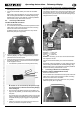
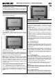
x Push the three gold-plated contacts into the plastic hou-
sing as far as possible; you should clearly hear them click
into place:
The smooth face of the gold-plated contact must coincide
with the underside of the plastic housing; this ensures that
the plastic retaining tongue engages in the gold-plated
contact.
x Check the connection once more: the three wires must
be firmly connected to the plastic housing.
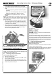
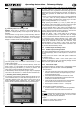
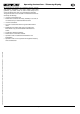
x Connect the UNI connecting lead, completed as described
above, to the “COM.” socket on the 2.4 GHz RF module:
This socket is located on the right-hand side of the 2.4 GHz
RF module. The pin assignment for the socket is also printed
at this point:
Pin assignment:
Signal (
) = yellow wire
Positive ( + ) = red wire
Negative ( - ) = black wire
! Note: if necessary you can also use the UNI extension
lead supplied in the set.
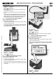
x Connect the transmitter battery and close the transmitter
case:
Ensure that no wires are trapped. You may need to secure the
UNI connecting lead attached to the Telemetry Display using
adhesive tape or one or more cable-ties. It must be possible to
close the case evenly, without force or tension.
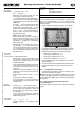
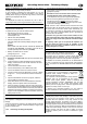
9. CONTROLS AND CONNECTIONS
The Telemetry-Display is controlled using the three buttons
DOWN (
), UP () and SET ( SET ) located on the front face
of the device.
The left-hand side of the Telemetry-Display also features a
thumb-wheel which controls the volume of the integral loud-
speaker and the optional earphone (# 8 5071) (Î 16.):
x To increase volume: rotate the wheel upward.
x To reduce volume: rotate the wheel downward.
The left-hand side of the Telemetry-Display is also fitted with a
3.5 mm barrel socket for the earphone plug. If an earphone is
plugged into the socket, the loudspeaker is muted.
10. USING THE UNIT FOR THE FIRST TIME
The Telemetry-Display is automatically switched ON and OFF
when the transmitter ON / OFF switch is operated.
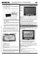
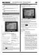
When switched ON, the following start-up screen is displayed for
about three seconds:
This display shows the following information at top right:
DISP = Firmware version of the Telemetry-Display.
HFM = Firmware version of the 2.4 GHz M-LINK module
or transmitter to which it is connected
After about three seconds the screen switches to the normal dis-
play, showing the last four selected telemetry values (Î 12.).
! Note: when you first switch the unit ON, the display switches
to the telemetry values 0, 1, 2, 3 (Î 12.1.).
Possible errors, fault-finding:
Error:
x The Telemetry-Display stays OFF when you switch the
transmitter ON.
Remedy:
x The UNI lead attached to the Telemetry-Display is connected
to the socket the wrong way round.
black
red
y
ello
w
Volume
control
Earphone
socket