
Operating instructions

Operating Instructions - Telemetry-Display
Page 21
Operating instructions - Telemetry-Display # 985 5310 (31.01.2012 PaCh) • Errors and omissions excepted. •
¤
MULTIPLEX
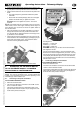
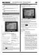
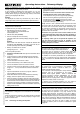
x Locate a plastic half-shell with recesses for the hexagon nuts
(1), and place it on the top left-hand corner of the handle.
x Fit three screws and three nuts to secure the two plastic half-
shells:
x This action clamps the gooseneck between the plastic
half-shells.
x Ensure that the Telemetry-Display wires are not trapped
between the shells when you tighten the screws.
! Caution: don’t over-tighten the screws – force is not
required!
! Tip: if the plastic shells do not fit tightly enough on the trans-
mitter handle, remove them again and wrap several layers of
clear adhesive tape round the bar where the plastic shells fit,
then re-attach them.
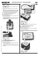
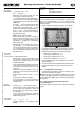
x Attach the remaining pair of plastic half-shells (1) and (2) to
the right-hand corner of the carry handle in the same man-
ner; the shell with the shaped recesses for the hexagon nuts
(1) should be on the underside:
x Fit the heat-shrink sleeve (supplied in the set) over the three
wires attached to the Telemetry-Display (overlapping the pro-
jecting part of the plastic mount). The heat-shrink sleeve
must not cover the gold-plated contacts:
x Carefully apply hot air to shrink the heat-shrink sleeve.
8. CONNECTING THE TELEMETRY-DISPLAY
TO THE 2.4 GHZ RF MODULE / TO THE MAIN
CIRCUIT BOARD OF THE TRANSMITTER
The three-core UNI connecting lead attached to the Telemetry-
Display can now be connected to the 2.4 GHz M-LINK RF
module, or the transmitter’s main circuit board, depending on the
transmitter type or RF module in use.
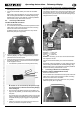
8.1. Connecting to Graupner transmitters
with the HFMG1 M-LINK RF module
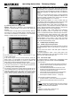
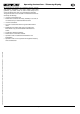
x Switch the transmitter OFF.
x The three-core UNI lead is connected to the “COM.” socket
of this 2.4 GHz RF module:
The socket is located above the “SET/LED” socket on the
right-hand side of the RF module. The pin assignment of the
socket is also printed at this point:
Pin assignment:
Negative ( - ) = black wire
Positive ( + ) = red wire
Signal (
) = yellow wire
! Note: if necessary you can also use the UNI extension
lead supplied in the set.
x Connect the transmitter battery, close the transmitter case:
Ensure that no wires are trapped when you do this. You may
wish to secure the UNI connecting lead attached to the Tele-
metry-Display with adhesive tape or one or more cable-ties.
It is important that the transmitter case can be closed evenly,
without tension or force.
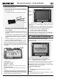
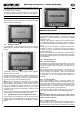
8.2. Connecting to Graupner transmitters
with the HFMG2 M-LINK RF module
x Switch the transmitter OFF.
x The three-core UNI lead is connected to the socket marked
“COM” on this 2.4 GHz RF module:
The socket is located above the “SET” socket at the right-hand
edge of the RF module’s circuit board. The pin assignment
for the socket is also printed at this point: