
Operating instructions

Operating Instructions - Telemetry-Display
Page 20
Operating instructions - Telemetry-Display # 985 5310 (31.01.2012 PaCh) • Errors and omissions excepted. •
¤
MULTIPLEX
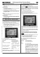
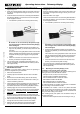
x Plastic shell with round recesses for the screw-heads (2):
! Note: the method of mounting the Telemetry-Display on the
handle of the listed Graupner/JR transmitters differs from the
method required for the listed MULTIPLEX transmitters.
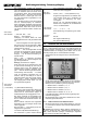
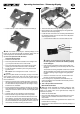
a) This is the procedure with the listed
Graupner/JR transmitters
x Switch the transmitter OFF.
x Place one plastic shell with recesses for the hexagon nuts
(1) on top of the left-hand corner of the handle.
x Place one plastic shell with round recesses for the screw-
heads (2) on the bottom left-hand corner of the handle.
x Fix the two plastic half-shells in place using three screws
and three nuts.
! Caution: don’t over-tighten the screws – force is not
required!
!
Tip: if the plastic shells do not fit tightly enough on the trans-
mitter handle, remove them again and wrap several layers of
clear adhesive tape round the bar where the plastic shells fit,
then re-attach them.
x Attach the remaining pair of plastic half-shells (1) and (2) to
the right-hand corner of the carry handle in the same manner.
The shell with the shaped recesses for the hexagon nuts (1)
should be on the underside.
x Fit the heat-shrink sleeve (supplied in the set) over the three
wires attached to the Telemetry-Display (overlapping the strain
relief); the heat-shrink sleeve must not cover the gold-plated
contacts.
x Carefully apply hot air to shrink the heat-shrink sleeve.
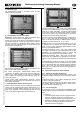
x Either on the left or right-hand side of the carry handle:
Locate the three wires of the UNI lead attached to the Tele-
metry-Display, and pass them through the large hole in the
top of the mounting block you have just fitted, then cautiously
screw the threaded part of the gooseneck into the mount; do
this carefully and without exerting excessive force:
x Thread the three wires through the large hexagon nut.
x Fit the hexagon nut on the threaded part of the gooseneck
attached to the Telemetry-Display.
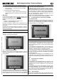
x Locate the ends of the three-core connecting lead attached to
the Telemetry-Display, and connect them to the UNI plastic
socket supplied in the set:
x It is essential to position the connecting lead correctly:
!
Caution: on no account mix up the positive, nega-
tive and signal wires, otherwise the Telemetry-Display
will be damaged!
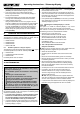
x Push the three gold-plated contacts into the plastic hou-
sing as far as possible; you should clearly hear them click
into place:
The smooth face of the gold-plated contact must coincide
with the underside of the plastic housing; this ensures that
the plastic retaining tongue engages in the gold-plated
contact.
x Check the connection once more: the three wires must
be firmly connected to the plastic housing.
x The connecting lead, completed as described above, can
now be connected to the transmitter’s RF module (continue
with Chapter Î 8.).
b) This is the procedure with the listed
MULTIPLEX transmitters
! Note: this section describes the method of fitting the Tele-
metry-Display on the left-hand side of the MULTIPLEX carry
handle. If you prefer to fit it on the right-hand side, modify the
procedure as required.
x Switch the transmitter OFF.
x Place one plastic half-shell with round recesses for the screw-
heads (2) on the underside of the left-hand corner of the
carry handle.
x Fit the threaded section of the gooseneck in the recess in the
half-shell as far as it will go.
x Extend the three wires attached to the Telemetry-Display in a
straight line.
black
red
y
ello
w