
Operating instructions

Operating Instructions - Telemetry-Display
Page 18
Operating instructions - Telemetry-Display # 985 5310 (31.01.2012 PaCh) • Errors and omissions excepted. •
¤
MULTIPLEX
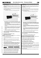
x Sound output:
Via the integral loudspeaker or the optional earphone
(# 8 5071), for audible feedback “right in your ear”!
x Vario sound output can be switched ON and OFF:
Either using the SET button on the Telemetry-Display or
directly at the transmitter.
x The Telemetry-Display can generate visual and audible
warnings when individually set thresholds are reached.
x Update-capable, future-proof:
Using the “MULTIPLEX Launcher” PC program. This PC
program is available as a free download from www.multiplex-
rc.de. The following items are required for updating: USB
PC-lead, UNI (# 8 5149) in conjunction with the sensor Y-
lead (three UNI connectors). This powers the Telemetry-
Display during the update process, and is also available
under (# 8 5090).
6. HARDWARE AND FIRMWARE UPDATES
6.1. Hardware and / or firmware updates not required
The following 2.4 GHz RF modules require no update, and can
immediately be connected to the Telemetry-Display:
x HFMG1 M-LINK
x HFMG2 M-LINK
x HFMG3 M-LINK
x HFMx V2 M-LINK
6.2. Hardware update is or may be required
The following 2.4 GHz RF modules and transmitters may
require
a hardware update for use with the Telemetry-Display:
x HFM3 M-LINK
x COCKPIT SX M-LINK transmitter
x HFM4 M-LINK
For details please refer our website.
7. ATTACHING THE TELEMETRY-DISPLAY
TO THE TRANSMITTER
7.1. Prior considerations
The Telemetry-Display is designed to be mounted in a
vacant switch well or on the transmitter’s carry handle,
according to transmitter type.
These installation options are described in the following
chapters:
- “Mounting in a vacant switch well”:
Î using the mc-24 transmitter as an example.
- “Mounting on the handle” of a Graupner/JR transmitter:
Î using the mx-24s transmitter as an example.
- “Mounting on the handle” of a MULTIPLEX transmitter:
Î using the ROYALpro M-LINK transmitter as an example.
If you intend to mount the Telemetry-Display on a dif-
ferent transmitter type, you can still follow the general
procedures as described in these instructions.
Right at the outset you need to consider the optimum position of
the Telemetry-Display to suit your purpose. The following points
should be considered in particular:
x You must ensure that there is “unobstructed line of sight”
between the 2.4 GHz aerial and the model at all times.
The Telemetry-Display must not obstruct the 2.4 GHz
aerial on the transmitter under any circumstances!
x It must be possible to rotate and angle the 2.4 GHz aerial to
produce an optimum signal radiation pattern even when the
Telemetry-Display is in place.
x Once installed, the Telemetry-Display must not restrict ac-
cess to switches, sliders, rotary knobs …, nor the legibility of
the transmitter meter or screen.
x The UNI connecting lead has to be plugged into the RF mo-
dule or the transmitter’s main circuit board, depending on the
transmitter type. Note that the extension lead supplied in the
set can be used if necessary.
x If the optional earphone (# 8 5071) is to be used, you should
also consider at this point how best to route the lead from the
Telemetry-Display to your ear.
7.1.1. Mounting the Telemetry-Display in a vacant
switch well
One option is to install the Telemetry-Display in any vacant
switch well on the left or right-hand side of the transmitter.
This method of mounting is recommended for the following
transmitter types and 2.4 GHz M-LINK RF modules:
x Graupner mc-18, mc-20 and mc-24
with the HFMG1 M-LINK 2.4 GHz RF module.
x Graupner mc-19, mc-19s, mc-22 and mc-22s
with the HFMG2 M-LINK 2.4 GHz RF module.
x MULTIPLEX PROFImc 3010, PROFImc 3030
and PROFImc 4000
with the HFM3 M-LINK 2.4 GHz RF module.
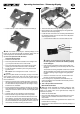
a) This is the procedure with the listed
Graupner transmitters
! Note: if you are uncertain about any point, please refer to the
operating instructions supplied with your transmitter.
x Switch the transmitter OFF.
x Carefully open the transmitter case and remove the back
panel.
x Disconnect the transmitter battery (short-circuit hazard).
x Remove the blind grommet from the well in which you intend
to install the gooseneck.
x Slip the heat-shrink sleeve (supplied in the set) over the
three connecting wires attached to the Telemetry-Display.
Note that the gold-plated contacts must not be covered by
the heat-shrink sleeve.
x Carefully blow hot air over the heat-shrink sleeve to shrink it.
x If necessary, open up the hole in the switch well to a
diameter of about 6.5 mm, using a round file or drill bit:
The hole is large enough when the threaded part of the
gooseneck fits through it.
! Note: keep any metal swarf and / or plastic waste well
away from the electronics and mechanical parts. Please take
as much care as possible to remove all waste material.
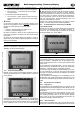
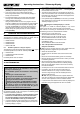
x Locate the three wires attached to the Telemetry-Display and
pass them through the prepared hole from the outside: