
User Manual


Seite 16
5. Completing the tailplane (KIT)
First t the sleeve 38 in the tailplane spar 67 before gluing this
assembly into the upper tailplane shell 16. Glue the four exible
hinges 32 in place at the points shown. The upper and lower tail-
plane shells (16 & 17) can now be glued together.
Figs. 33 + 34
Glue the elevator joiner tube 61 and the balsa spars 68 in the upper
elevator shell 18. The upper elevator shell can now be glued to the
lower shell 19, taking care to avoid glue running into the hinge slots.
Glue the elevator horn 30 in the recess in the elevator, and press
the swivel pushrod connector 83 and socket-head grubscrew 84
into the horn. For the rst few ights we recommend connecting the
pushrod to the outer hole in the horn, as the Extra is an extremely
responsive aircraft in the air.
Figs. 35 + 36
Using the at-tipped Zacki nozzle again, apply glue to the hinge
slots in the elevator, and press it onto the hinges and against the
tailplane, leaving a hinge line gap about 0.5 mm wide.
Figs. 37 + 38
6. Completing the rudder (KIT)
Glue the two clip-hinges B 34, the rudder bush 37 and the balsa
spar 66 in the right-hand rudder shell 21. Glue this assembly to
the left-hand rudder shell 20. Glue the horn 31 in the recess of the
rudder, then clip the swivel pushrod connector 83 and socket-head
grubscrew 84 into the horn.
Figs. 39 + 40
7. Assembling and installing the undercarriage (KIT + RR)
Press a self-locking nut 80 into the right-hand inboard wheel spat
shell 48. Fit an axle (machine screw) 78 through the right-hand
outboard wheel spat shell 47, then slip the wheel 53 onto it. Engage
the axle (screw) in the nut, then x both wheel spat shells together
using the self-tapping screws 81. Repeat the whole procedure to
complete the left-hand wheel spat.
Fig. 41
Attach the undercarriage fairings 23 & 24 to the main undercarriage
unit 58, applying the Zacki sparingly. Take care to t the parts the
correct way round; the undercarriage is swept back at the leading
edge, while the fairings are bevelled at the front to follow the line
of the lower air outlet.
Fig. 42
The wheel spats can now be xed to the undercarriage using a
washer 79 and nut 86 on each side, at the same time xing the
assembly to the fuselage using the retaining screws 82. Apply a
drop of medium-strength thread-lock uid to the screws 82 when
you tighten them.
Figs. 43 - 45
8. Attaching the tailplane to the fuselage (KIT + RR)
Slide the tailplane into the slot in the fuselage, and secure it with
the plastic retaining screw 73 from the underside. Use a servo
tester or your RC system transmitter to centre the elevator servo,
and set the elevator exactly to neutral (centre) before tightening
the socket-head grubscrew 84 in the swivel pushrod connector.
Tighten the screw rmly. Push the in-ll piece 22 into the tail end
of the fuselage, and secure it with a small strip of adhesive tape
on each side.
Figs. 46 – 48
Fit the bottom of the rudder into the lower bush and push the
clip-hinges together to engage them; each hinge must audibly
“click” into place. Use a servo tester or your RC system transmitter
to centre the rudder servo. Check that the rudder is also at neutral
(centre) before tightening the socket-head grubscrew 84 in the
swivel connector. Tighten the screw rmly.
Figs. 49 – 51
Insert the tailwheel unit 62 in the skid support, then glue the in-ll
piece 36 in place with a little Zacki. Note that the wire tailwheel unit
must remain free to swivel (apply glue at the front only).
Slip the collets 85 and the tailwheel 54 onto the axle. Apply a drop
of medium-strength thread-lock uid to the retaining grubscrews
84, and tighten them rmly.
Figs. 52 + 53
9. Completing the canopy (KIT)
Glue a magnet 86 in each of the magnet supports 40, then glue
these assemblies in the canopy frame 7 in the positions shown.
Please ensure that the positive and negative poles of the magnets
are orientated correctly relative to those in the fuselage, so that the
magnets attract each other. It is a good idea to paint the inside of
the cockpit light grey, and this is a good time to do so. We always
recommend that the internal space should not be painted a dark
colour, as strong sunshine could be magnied by the clear cano-
py and cause the Elapor foam to distort if it is too dark. Glue the
instrument sticker 90 to the instrument panel. Paint the dummy
pilot 25 in the colours of your choice (waterproof felt-tip pens also
work very well) before gluing him in the cockpit. The clear canopy
52 is best glued to the frame using UHU
®
POR; please take care
to achieve a neat glued joint. The nal task is to glue the canopy
latch A 41 at the rear of the canopy using Zacki; again take care
to ensure that the latch can be pulled forward and springs back
by itself.
Figs. 54 – 58
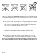
10. Installing the motor (KIT + RR)
Apply medium-strength thread-lock uid to the retaining screws
before attaching the cruciform mount to the PERMAX-BL O 3520-
0920 motor. Connect the motor to the MULTIcont BL 55 S-BEC
speed controller, and check the working system from your trans-
mitter: hold the motor rmly by the cruciform mount and open the
throttle very slightly, so that you can check the direction of rotation
of the output shaft: when viewed from the front, the motor must
rotate anti-clockwise. If this is not the case, swap over any two
wires between the speed controller and the motor. Now slip the
speed controller into the fuselage before permanently screwing
the motor to the M-frame.
Figs. 59 + 60
11. Fitting the propeller (KIT + RR)
Before carrying out this stage we recommend that you check the
balance of the propeller using the balancing device # 33 2355.
An accurately balanced propeller is the basic essential for smooth
running, and at the same time avoids premature damage and wear
to the motor bearings and the airframe as a whole.
Assemble the propeller adapter (included in the power set) using
medium-strength thread-lock uid to secure the parts. Now slip
the spinner backplate 78, the 14 x 7” propeller (in the power set)
followed by the prop washer (in the power set) onto the shaft, and
tighten the retaining nut (in the power set) rmly to clamp the parts
together. Fit the spinner cap 27 on the front and secure it with the
retaining screws 76.
Fig. 61
12. Applying the decals
The rst step here is to wipe the model all over using methylated
spirits (‘meths’) to remove every trace of grease. The kit is supplied
complete with three decal sheets A, B & C. The individual graphics
and name placards are pre-cut, and just need to be applied to the
model in the arrangement shown in the kit box illustration. The
rudder decal and the graphic which overlaps the canopy and the
fuselage require special attention. This is the procedure: rst t
the canopy on the fuselage and ensure that it is a snug t, and
properly closed; make any adjustments required. Install the rudder
and set it to centre. Now apply the graphics in the positions shown.
When they are in place, slit along the joint line between canopy and
fuselage, and between rudder and n, using a sharp (preferably