
User Manual


Seite 15
Congratulations on your new EXTRA 330SC!
You will need the following tools to complete the model:
2 x Zacki
®
Elapor # 85 2727
Activator spray for cyano-acrylate adhesive
Medium-strength thread-lock uid
UHU
®
POR
Clear adhesive tape
Large and small cross-point screwdrivers
Balsa knife
Pointed-nose pliers
1.5 / 2.5 / 3.0 mm allen keys
5.5 mm & 10 mm A/F open-ended spanners
1 sheet 320-grit abrasive paper
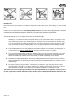
Before you start building:
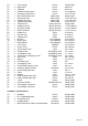
Check that all the specied parts are present by comparing the
contents with the Parts List on page 18, and Figs. 01 + 02
To prevent the airframe components being scratched and dented
during construction we recommend assembling the model on a
perfectly straight, clean bench with a soft surface. Unless ex-
pressly stated otherwise, use Zacki
®
Elapor cyano-acrylate glue
for all joints.
1. Preparing and joining the fuselage shells (KIT)
Use Zacki to glue the tailplane / tailskid support 35 in the right-hand
fuselage shell 6. Glue the nut support 39 and the clip-hinge A 33
in place at the same time.
Now t the elevator pushrod 64 and the outer sleeve 57 in the same
fuselage shell. Temporarily place the M-frame 69 in the fuselage to
allow you to establish the correct position of the sleeve: it should
end ush at the tail end, and engage in the hole in the M-frame’s
guide former to a depth of about 4 mm. Glue the outer sleeve to the
shell at the tail end and the upper of the two channels using Zacki.
Figs. 03 – 06
The M-frame can now be glued in the right-hand fuselage shell
using Zacki. Please ensure that you apply adhesive to all the joint
edges of the M-frame, and that it makes good contact with the
Elapor foam at all points.
Fig. 07
Now glue the outer sleeve 56 and the rudder pushrod 63 in the
left-hand fuselage shell 5 exactly as described for the right-hand
shell. Once again, check that the sleeve ends ush at the tail end,
and engages in the hole in the M-frame’s guide former frame to
a depth of about 4 mm.
Figs. 08 + 09
Very lightly sand the mating surfaces of the two fuselage shells,
taking great care not to damage the external edges. Apply Zacki
to the joint surface of the right-hand fuselage shell, leaving a gap
about 4 mm wide to the outside edge, so that excess adhesive is
not squeezed out of the joint; this could spoil the nish when the
shells are joined.
Now place the two fuselage shells together and check carefully
that both line up accurately along the joint lines. It is important
that the fuselage is not warped or twisted. When you are satised
that all is well, apply a very little activator spray along the outside
joint lines to cure the adhesive. Please observe the safety notes
supplied by the spray manufacturer.
Fig. 10
2. Attaching the supplementary parts to the fuselage, install-
ing the fuselage servos (KIT)
Glue the canopy latch B 42 to the fuselage using Zacki. Glue
one magnet 86 in each of the magnet supports 40, and glue the
supports in the fuselage at the points shown. Don’t use excessive
adhesive which could be forced out of the joints, and ensure that
the magnets and holders are positioned ush with the top edge
of the canopy opening. Apply a strip of adhesive tape over each
of the magnets to keep them permanently in place.
Figs. 11 - 13
Paint the dummy exhaust 26 and the air intake grille 29 in a silver
or bronze colour, allow the paint to dry, then glue these parts to
the chin intake and lower outlet.
Figs. 14 + 15
Use a servo tester or your RC system transmitter to centre two
Hitec HS-82MG servos. Screw the HD-LS output lever 91 to the
elevator servo output shaft, and a prepared HD-IS output lever 92
(cut in half) to the rudder servo output shaft. Screw the two servos
to the M-frame using the anged retaining screws 75: the rudder
servo must be on the right, as seen from the tail, with the output
shaft to the rear, while the elevator servo is on the left, with the
output shaft to the front.
Figs. 16 + 17
Glue the cross-brace 72 in the fuselage.
Fig. 18
3. Completing the wing panels (KIT)
The rst step is to glue the tubular spar
60 in the right-hand upper
wing panel 10, taking care to minimise the glue which is forced out
of the channel. Glue the servo frame 44 and four exible hinges
32 in the shell at the positions shown. Lightly sand the mating
surfaces, then offer up the upper wing panel to the lower wing
panel 11 and check that the parts t together snugly. When you
are satised, apply adhesive to the joint surfaces of the upper wing
panel, and press the two panels together. Check carefully that the
wing is not warped, and that no glue is squeezed out of the joints;
wipe away any excess with a piece of paper towel.
Figs. 19 – 22
Glue together the aileron shells 14 & 15 using Zacki, taking care
to avoid glue running into the hinge slots. Glue the aileron horn
30 in each aileron. At this point you can press the swivel pushrod
connectors 83 into the horns after tting a socket-head grubscrew
84 in each. For the rst few ights we recommend that you con-
nect the pushrods to the outer hole of the horns, as the Extra is
an extremely responsive aircraft in the air.
Fig. 23
Use a pair of pliers to atten the tip of the Zacki bottle to enable
you to apply adhesive to the inside of the aileron hinge slots. It is
important to work as neatly as possible here, to ensure that the
ailerons are attached securely and permanently to the wing. When
you have applied glue to all the hinge slots, push the ailerons onto
the hinges and against the wing, leaving a hinge line gap about
0.5 mm wide.
Fig. 24
Glue the wing retainer doubler 49 in place.
Fig. 25
4. Installing the aileron servos and linkages (KIT)
Use a servo tester or your RC system transmitter to centre one
Hitec HS-82MG servo, then screw the HD-LS output lever 91 on
the output shaft. Connect a 15 cm extension lead # 85019 to the
servo lead, and apply a strip of adhesive tape or a drop of Zacki
to the connectors to prevent them working loose under tension.
Thread the servo lead through the channel in the wing and press
the servo into the recess. Screw the servo well cover 43 in place
using the retaining screws 77. Connect the aileron pushrod 65 to
the third hole from the outside of the servo output arm, then slip
it through the swivel connector tted to the aileron horn. Check
that the servo and the aileron are both at neutral (centre) before
permanently tightening the socket-head grubscrew 84. Repeat
the procedure with the left-hand wing and aileron. Figs. 26 – 31