
Instructions


21
The basics of model ying
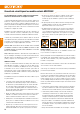
Wing section (airfoil)
The wing has a curved (cambered) cross-section, known as an airfoil,
over which the air ows when the model is ying. In a given time the air
above the wing covers a greater distance than the air below the wing.
This results in a reduction in pressure over the top surface of the wing,
generating an upward force (lift) which keeps the aircraft in the air.
Fig. A
Centre of Gravity
Like any other aircraft, your model aeroplane must be balanced at a
particular point if it is to have stable ying characteristics. It is absolutely
essential to balance the model correctly before its rst ight. The balance
point, or Centre of Gravity (CG), is stated as a linear distance measured
from the wing leading edge, close to the fuselage. When supported at
this point on your ngertips, or - preferably - using the MPX CG gauge,
#693054, the model should balance level.
Fig. B
If the model does not balance at the marked point, this can usually be
corrected by re-positioning the airborne components (e.g. ight battery). If
this is not sufcient, the correct quantity of ballast (lead or modelling clay)
should be xed securely to the nose or tail of the fuselage. If the model
is tail-heavy, t the ballast at the fuselage nose; if it is nose-heavy, attach
the ballast at the tail end of the fuselage.
Neutral point
The neutral point of an aircraft is the point at which the aerodynamic
forces are in equilibrium. If an aeroplane ies in a stable attitude, then
its neutral point is always aft of the Centre of Gravity. Any aircraft whose
Centre of Gravity is aft of the neutral point will be inherently unstable in
the air. Manual control of an aircraft trimmed in this way is impossible; it
requires a computer system for stabilization and control.
Longitudinal dihedral
This term refers to the difference in incidence between the wing and
the tailplane. Provided that you t and secure the EasyStar 3’s wing
and tailplane to the fuselage as stated in these instructions, then the
longitudinal dihedral will automatically be exactly correct. If these two
settings (centre of gravity and longitudinal dihedral) are correct, you will
encounter no problems when ying your aeroplane, especially at the test-
ying stage.
Fig. C
Control surfaces and control surface travels
The model can only y safely and precisely if the control surfaces are
free-moving, operate in the correct “sense” (direction relative to stick
movement), and are set up to deect by the appropriate amount. The
control surface travels stated in the building instructions have been
established by a test-ying programme, and we recommend that you
adopt these settings initially. You may wish to adjust them subsequently
to suit your personal preferences.
Transmitter control functions
The radio control system transmitter is tted with two primary sticks
which cause the servos - and therefore the model’s control surfaces - to
deect when moved. The stated function assignment is correct for stick
mode A, but other stick modes are possible.
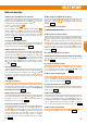
The following control surfaces are controlled from the transmitter:
The rudder (left / right)
Fig. D
The elevator (up / down)
Fig. E
The throttle (motor off / on)
Fig. F
The ailerons (left / right)
Fig. G
The stick which controls the throttle (motor speed) must not be of the self-
centring type. It is usually tted with a ratchet which operates over the
full stick travel. How this setting works you can read up in the operating
instructions supplied with your radio control system.
EN