
Instructions


17
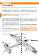
16. Installing the tailplane frame
To guarantee a secure seating, the tailplane frame
㊼
must be glued in
the recess of the tailplane
6
.
Fig. 18
17. Attaching the tailplane
First withdraw the tailplane slider
㊽
slightly, then insert the tailplane
6
and push the slider back in as far as it will go to secure the tailplane.
Donot glue it! The tailplane should be left detachable for safe, convenient
transport. To remove the tailplane, press the tailplane clips
㊹
together
with two ngers, and at the same time pull the tailplane slider
㊽
down;
the tailplane can now be removed.
Fig. 19
18. Connecting the elevator
Slip the inner pushrod for the elevator through the hole in the swivel barrel
㉓
, and check the servo neutral position once more before tightening
the allen-head grubscrew
㉔
. We recommend that you apply a drop of
medium-strength thread-lock uid to the grubscrew to prevent it working
loose over time.
Fig. 20
19. Releasing the control surfaces
Use a sharp balsa knife to remove the foam at the lateral ends of the
control surfaces, cutting along the moulded-in channels. Repeatedly
move the control surfaces to and fro in order to loosen the integral hinges
and render them freemoving. Do not separate the control surfaces!
Fig. 21
20. Attaching the servo well covers
Press the left and right servo well covers
⓫
and
⓬
into the openings in
both sides of the fuselage. They should not be glued in place, as you may
have to replace the servos at some time.
Fig. 22
21. Installing the wing joiner channel cover
Carefully glue the wing joiner channel covers
9
and
⓾
in the wing
panels
7
and
8
. Take particular care to avoid glue running onto the
surfaces which will later make contact with the wing joiner
㊿
. Check
that the wing joiner
㊿
is a snug t in the wings, but only when you are
absolutely condent that there is no active adhesive inside the channel.
If you neglect this, you could nd that the model is glued together
permanently.
Fig. 23
22. Attaching the rudder horns to the aileron
Recesses of the ailerons on the wings
7
+
8
. Screw both counter
plates
㉒
/
1
through the rudder horns using two screws each
㉒
/
4
.
Fig. 24
23. Preparing the aileron servos
See “10. Preparing the servos”.
24. Installing the aileron servos
Fit the pre-formed aileron pushrods
㉖
through the second hole from
the outside of the servo output arms. Use hot glue to glue the servos into
the recesses and feed the servo cables in the cable ducts through the
wings. Feed the aileron pushrod with “Z”
㉖
into the cardan bolt. Check
once more that the servos are at centre before tightening the grubscrews
㉔
in the swivel barrels. We recommend applying a drop of medium-
strength thread-lock uid to the grubscrews to prevent them working
loose.
Fig. 25
25. Servo lead length, aileron connections
Draw the servo leads out of the wings
7
+
8
where the wing meets
the fuselage.
Fig. 26
26. Installing the cable sleeves
To avoid kinking the aileron servo leads, glue 18 mm lengths of snake
outer sleeve (3 mm Ø / 2 mm Ø) in the recess where the cables exit the
wing.
Fig. 27
27. Installing the firewall
Glue the rewall
㊵
in place using thick cyano. Don’t use activator for
this joint, as you will need a certain amount of time to position and align
the rewall correctly.
Fig. 28
28. Gluing the cowl screw support in place
Glue the cowl screw support
㊷
at the front end of the motor pod.
Fig. 29
29. Installing the motor
Fix the motor in place using two M3 x 6 screws. Apply a drop of medium-
strength thread-lock uid to the screws. The cable outlet on the motor
points to the right in the direction of ight. The motor cables are laid
behind the glued-in cable guide.
Fig. 30
30. Installing the motor cowl
Fit the three screws
㉚
to secure the motor cowl
㊶
.
Fig. 31
31. Assembling the propeller
Attach the propeller blades
to the propeller boss
using the two
dowel pins 62.
Fig. 32
Slip the taper collet through the driver
and place this assembly in the
propeller boss
. The washer
and the shakeproof washer
are
tted from the other side. Screw the M6 nut
on the taper collet
.
Fit the taper collet
on the motor shaft and tighten the nut rmly before
tting the spinner.
Fig. 33 + 34
Fit the O-ring
through the spinner cone
.
Fig. 35
Assembly instructions
EN