
Instructions


16
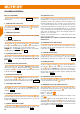
Before you start building
Check the contents of your kit. You will nd
Fig. 1, 2 + 3
and the Parts
List helpful here.
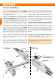
1. Cutting the snake outer sleeves
Use a sharp balsa knife to cut the snake outer sleeves
(3 mm Ø) to
the lengths shown in
Fig. 3
. The snake inner tubes
(2 mm Ø) are
supplied ready to install.
2. Guiding motor pod cables
Glue the 31 mm length of snake outer sleeve inside the motor pod using
cyano.
Fig. 4
3. Installing the tailplane lock
Glue the tailplane clip
㊹
, the upper tailplane sleeve
㊺
and the tailplane
frame
㊻
in the right-hand fuselage shell
4
: spray activator thinly on
the plastic parts, and allow a few seconds for the uid to air-dry.
CAUTION! Take care not to glue together the two plastic parts (tailplane
clip
㊹
and upper tailplane sleeve
㊺
)!
Fig. 5
4. Inserting the tailplane slider
Allow the glue to set hard, then insert the tailplane slider
㊽
to ensure
that the parts are accurately aligned. This part must not be glued in
place!
Fig. 6
5. Reinforcing the bottom of the fuselage
Cut the outer snake sleeve to a length of 635 mm, then glue it in the
channel in the bottom of the right-hand fuselage shell
4
. Temporarily t
the tailplane slider
㊽
to position this part accurately, but take care not
to glue the parts together.
Fig. 7
6. Reinforcing the fuselage nose
Cut the sleeves to a length of 247 mm, and glue them in the upper part of
the two fuselage shells
3
+
4
. Cut the sleeve to a length of 290 mm
and glue it in the underside of the right-hand fuselage shell 4.
Figs. 8 + 9
7. Preparing the cable holders
Glue the plug end of the 30 cm extension lead # 8 5031 to the cable
holder
㉙
, ush with the edge. Push the cable under the lug on the
underside.
Fig. 10
8. Installing the cable holders
First spray activator on the joint surfaces of the cable holders
㉙
. Allow
the uid to air-dry, then glue the parts in the appropriate recesses in both
fuselage shells.
Fig. 11
9. Gluing the latch catches in place
Glue the latch catches
㉗
in both fuselage shells. Once again, spray
activator onto the plastic part, and allow it to air-dry.
Fig. 12
10. Preparing the servos
Before installing the servos, set all of them to neutral (centre) from the
transmitter: this is accomplished by connecting the servo to a receiver,
switching the system on, and centring the stick at the transmitter; check
that the transmitter trims are also at neutral. Locate the “double-ended”
servo output levers with three holes per side, and t them on the servo
output shafts at right-angles to the long side of the servo cases. If you nd
that the output arm is not accurately at right-angles to the case when the
servo is at neutral, rotate the lever through 180° and try again; the output
shaft features an odd number of splines, and reversing the output device
will get you “closer to the target”.
Install the elevator and rudder servos as a mirror-image pair; the same
applies to the aileron servos.
Avoid moving the servo output levers by hand, as this can easily
ruin the gears!
11. Installing the servos in the fuselage
Use hot glue to glue the servos into the corresponding recesses in
the fuselage, with the output arms facing down, and the output shafts
towards the nose.
Fig. 13
12. Joining the fuselage shells
Spray the joint surfaces of one fuselage shell with cyano activator, apply
medium-viscosity cyano to the joint surfaces of the other shell, then
briskly join the two shells. Take care to align the parts accurately.
Fig. 14
13. Installing the snakes
Slip the pre-formed steel pushrods
for the elevator and rudder into
the inner tubes
(550 mm), and t these into the prepared outer
sleeves
, which are 523 mm long. Connect the pre-formed end of
the pushrod to the second hole from the outside of the servo output arm.
Glue the snake outers in the appropriate channels, running cyano right
along the channel.
Fig. 15
14. Preparing the control surface horns
Fit the allen-head grubscrews
㉔
in the swivel barrels
㉓
. Engage the
prepared swivel barrels in the horns
㉒
(4x each).
15. Attaching the horns to the rudder and elevator
Apply instant adhesive to the recesses of the foam parts in the area of
the thickenings. Position the rudder horns
㉒
and the counter plates
according to the number embossed on the back:
Elevator -> counter plate
Rudder -> counter plate
Screw the counter plates through the rudder horns using two screws
each .
Slip the steel pushrod for the rudder linkage through the hole in the
swivel barrel
㉓
. Check once more that the servos are at centre before
tightening the allen-head grubscrews
㉔
. We recommend that you apply
a drop of medium-strength thread-lock uid to each grubscrew to prevent
them working loose over time.
Fig. 16 + 17
Assembly instructions
EN