
Instructions


27
Building instructions
The nal step is to rub the whole area of the decal down onto the model’s
surface using a soft cloth, taking care not to trap air bubbles.
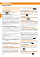
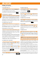
The two clear decal strips (approx. 35 x 800 mm) are intended as
protection for the wing leading edges, and are especially useful for pilots
who have to land in long grass at the slope. This is the procedure for
applying them: stand the wing panel on its trailing edge, support the wing
in that position with a stack of books on one side, then apply the strip to
the centreline of the leading edge. Carefully wrap the strips round onto
both surfaces of the wing. At the dihedral break cut out a narrow “V” using
a sharp knife to avoid creases.
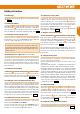
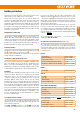
50. Applying the landing skid
The kit includes a landing skid
made of special heavy-duty self-
adhesive lm, which should be applied to the underside of the fuselage
at the nose. The lm begins just aft of the spinner, and should be centred
over the fuselage joint line. Once in place, rub it outwards on both sides,
avoiding creases. If you have installed a retract unit, you will need to cut
through the lm again over the wheel well, working carefully.
51. Battery retention
The battery is secured in the model using the hook-and-loop tape
and
, together with the hook-and-loop strap
.
The strap can be passed through one of the three slots in the front of the
fuselage, under the rectangular tube.
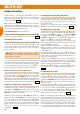
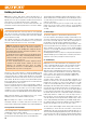
52. TEK-Vario + TAS (TrueAirspeed) sensor
The Lentus is prepared as standard for the installation of the Multiplex TEK-
Vario + TAS (TrueAir-speed) sensor. The unit can be installed in just a few
minutes - even in the factory-built RR version of the model - and provides
you with airspeed and climb / rate information at all times. It is also possible
to dene minimum and maximum values, and set warning thresholds.
Installation:
The electronic unit is installed in the fuselage at the nose, in the recess aft
of the speed controller. The next step is to cut the hoses to the required
length; this is easiest to do at the pitot tube end. But take care: it is
essential not to mix up the hoses, so mark them and re-connect them
immediately. With the rudder removed, slide the pitot tube forward
through the hole in the recessed rudder hinge line, in the upper third of
the n. Fit a thin screwdriver or similar tool between the connections on
the back of the unit, and push the tube forward. The pitot tube should then
project forward over the fuselage for a distance of about 30 mm. Route
the two hoses through the 20 mm Ø tube in the fuselage using a suitable
tool (e.g. steel rod), and deploy them in the left and right channels in the
rudder hinge recess at the tail end, taking care to avoid kinks (i.e. keep
the hoses smoothly curved). Secure them with small pieces of adhesive
tape, then re-install the rudder.
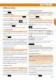
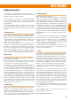
53. Setting the Centre of Gravity
Like every aircraft, large or small, your new model must balance at a
particular point if it is to offer stable ying characteristics. Assemble your
model completely, ready to y.
The Centre of Gravity is marked at a point 67 mm aft of the wing
root leading edge (moulded-in domes on the underside). If you support
the model on two ngers at these two points, it should bal-ance level.
Adjust the position of the ight battery to achieve this, and - if necessary
- press the trim weight
(ball bearing) in the tail end of the fuselage.
We are unable to state exact ballast require-ments here due to tolerances
in material density and differences in equipment (battery) between the
glider and electric glider versions.
The pure glider version requires more ballast in the nose to compensate
for the lack of a motor. This can be stowed in the empty area aft of the
motor bulkhead, and is best secured using hot-melt adhesive or similar.
Once you have established the correct battery position, mark its location
inside the fuselage to en-sure that you always install the ight pack in the
same place.
Fig. 34
Tip: a convenient method of checking the C.G. is to use the Centre of
Gravity gauge Order No. 69 3054.
54. Setting the control surface travels (guideline only!)
The control surface travels must be set correctly if the model is to
respond in a harmonious manner to the controls. All the stated travels are
measured at the widest point of the control surface. Please note that the
stated values are just a guide, and you may wish to alter them to suit your
personal preference.
Elevator
up (stick back) approx. +11 mm
down (stick forward) approx. –11 mm
Spoiler (down-elevator) approx. – 3 mm
Electric version: throttle mixed to elevator – 1 mm
Flap mixed to elevator for Speed / Thermal approx. – 1 / 1,5 mm
Rudder
left and right each approx. 35 mm
Ailerons
up / down
approx.
+ 24 / – 11 mm
Speed (up) approx. + 3 mm
Thermal (down) approx. – 3 mm
Spoiler (both ailerons up) approx. + 24 mm
Flap (camber-changing flaps)
Aileron support (aps up only) approx. + 10 mm
Speed (up) approx. + 4 mm
Thermal (down) approx. – 4 mm
Spoiler (aps down) approx. – 26 mm
Spoiler (Butterfly / Crow) with additional transmitter offset - permits
even greater travels!
both ailerons up approx. + 30 mm
both aps down approx. – 30 mm
Spoiler mixed to elevator approx. – 4 mm
You may need to re-adjust the control surface linkages.
EN