
Instructions


25
Building instructions
round to conceal the joint line. We recommend high-ex grey adhesive
tape for this.
Fig. 22
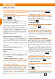
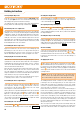
30. Completing the tailplane
Glue the tailplane spreader
to the top of the tailplane.
Fig. 23
Glue the CFRP spar
(6 x 1.5 x 400 mm) in the channel on the
underside of the tailplane
. Ap-ply a drop of hot-melt adhesive to both
ends to ll any gaps, leaving the surface ush.
Fig. 24
Glue the elevator horn
to the underside of the elevator. It is essential
to position it the right way round! Do not allow glue to enter the
transverse pushrod hole.
Fig. 24
Move the elevator up and down repeatedly to free up the hinge line.
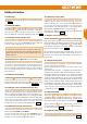
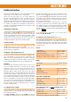
31. Installing the tailplane
Locate the pre-formed end of the elevator pushrod
and “thread” it into
the elevator horn
from the side; the tailplane can now be positioned
on the n.
Fix the tailplane to the top of the n using the two M5 x 35 mm plastic
screws
.
Fig. 25
Tip: rough ground at ying sites places severe stress on the exible
hinges, which may tend to tear over time. If this should happen, you can
reinforce them by tting at plastic hinges such as # 70 3202 (pack of 6).
This is the procedure: cut a slit exactly in line with the standard hinge,
then apply a little glue and push the at hinge into the slit. Ensure that the
pivot axis lines up exactly with the hinge line. Alternatively a thin layer of
silicone adhesive can also be effective.
32. Tubular spars in the wings
The wing spars are extremely strong, and consist of a carbon bre (CFRP)
prole enclosed in a precision-made extruded aluminium tube.
The tubular spars are already installed in the wings. Please inspect the
projecting ends, and carefully remove any rough edges using emery
paper, as this will make it easier for the spars to engage in the opposite
rib when the model is rigged.
The tubular spars are also reinforced and linked inside the wings by means
of several plastic components. On the underside of the wings you will nd
white plastic-lined holes which indicate where these parts are located.
If you have the KIT version of the model, a drop of Zacki ELAPOR
®
should
be applied through these openings in order to improve the connection
between the spar and the plastic reinforcement. Leave the glue to cure
fully before turning the wing over again!
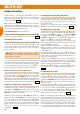
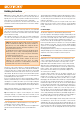
33. Fitting the root ribs
The rst step is to trial-t the ribs ‘dry’ - i.e. without glue. When you
are sure that everything ts, glue the root ribs
/
to the wings
using Zacki ELAPOR
®
, applying the adhesive to the full area of the joint.
Immediately press the ribs rmly against the wings using both hands.
Check that they t absolutely ush, and tape them in place until the glue
has set hard. Apply more Zacki to the round gap between the ribs and the
tubular spars.
Fig. 26
34. Installing the wing retaining clips
Position the retaining clips
inside the raised frame on the root ribs
(left) and
(right), and secure them using the screws
. Push
two 8 x 2 mm O-rings
over the retaining clips on each side to place
them under tension.
Fig. 27
35. Stiffening the ailerons + aps
The stainless steel stiffening tubes
(400 mm, 4 off) should be glued
in the appropriate spanwise channels in the wing control surfaces by
applying cyano adhesive along their full length. Secure the ends with a
little hot-melt glue.
Caution: do not apply adhesive to the horn recesses at this stage.
Fig. 28
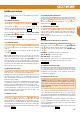
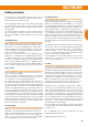
36. Preparing and securing the aileron / ap horns
Fit the socket-head grubscrews
in the barrel connectors
.
Fit the barrel connectors in the outermost holes of the aileron (QR / AI)
horns
. Avoid opening the horn lugs any more than necessary!
Fit the barrel connectors in the innermost holes in the flap (WK / Flap)
horns
.
CAUTION: the horns must be tted the correct way round!
Ailerons (QR / AI) => horns facing forward
Flaps (WK / Flap) => horns facing back
Apply hot-melt glue to the horn recesses, and immediately press the
horns fully into place. Apply more glue to the sides if necessary.
Figs. 29 + 30
37. Cutting free the ailerons + aps
Use a sharp knife or ne saw to cut through the inboard and outboard
ends of the aps and ailerons, then bend the control surfaces repeatedly
up and down to free up the hinges. Do not separate the control surfaces
by cutting along the hinge line!
38. Preparing the aileron servos
Caution: If you rotate the servo output lever through 180°, it will not
be at exactly the same angle due to the odd number of splines on the
servo shaft. To avoid problems, start by setting the output levers in the
optimum orientation, and only then cut off the unwanted arms to form
a mirror-image pair.
Centre each servo accurately from the transmitter, then t the output arm
on the shaft angled for-ward relative to the case by 1 spline. The two
servos should form a mirror-image pair. This setting provides mechanical
differential travel for the ailerons, i.e. the aileron up-travel is greater than
the aileron down-travel.
It is also possible to use the transmitter to adjust the servo output arms
to a non-central setting (Offset function). This will provide even greater
aileron up-travel, which in turn allows greater up-aileron for the buttery
(crow) landing function.
This is very helpful when you need to land the model in a conned area,
or where slope lift is present.
Fig. 29
EN