
Instructions


24
Building instructions
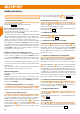
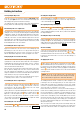
Working from the top, connect the rudder pushrod
(50 mm) to the
outermost hole in the servo output arm, centre the servo and rudder, and
tighten the retaining screw in the barrel connector to secure the pushrod,
using the allen key
.
Fig. 15
Tip: if you wish to disengage the rudder hinges and remove the rudder,
start by undoing the retaining screw in the barrel connector to release the
pushrod, then move the rudder to its maximum deection to the left. Now
move it a little further until the hinges disengage.
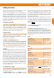
23. Installing the motor (if not already carried out)
Fit the motor in the motor bulkhead, with the cables located at bottom right.
Fix the motor to the bulkhead using the four screws and washers.
Fig. 17
24. Installing the speed controller
If you have already tted the propeller, remove it now. Connect the speed
controller, and check from the transmitter that the motor shaft spins in
the correct direction: when you look at the motor from the front, the shaft
must rotate anti-clockwise. If this is not the case, swap over any two of
the three motor wires.
Caution: Never connect the ight battery to the speed controller
before switching on your transmitter, and ensuring that the throttle
control is in the “OFF” position.
Fix the speed controller in the appropriate recess in the right-hand fuselage
shell using narrow strips of hook-and-loop tape or a little hot-melt adhesive.
Secure the cables to the cable-tie holders 24 with two cable-ties
. Route
the cables forward under the cross-strut to the motor, and secure them to
the bottom of the fuselage behind the motor using hot-melt adhesive.
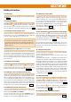
25. Aero-tow release for the electric glider version
The electric version of the model also features an aero-tow release, which
is an integral part of the motor bulkhead. If required, this can be actuated
by means of an additional servo # 112065. In this case the snake sleeve
and the steel push rod
required should be installed in the front
of the fuselage as shown. Shorten the pushrod to the point where it does
not foul the spinner backplate in the locked state (rod forward).
Fig. 17
26. Optional aero-tow release for the glider version
Alternatively the model can be completed as a pure glider. In this case the
optional glider nose # 224350 is simply glued to the front of the fuselage.
If you wish, you can install the optional central aero-tow release # 72
3470, which is designed for this application.
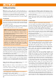
Installing the optional retractable wheel # 1-01759 This requires one
additional HS-85MG servo # 112086. The retract unit is supplied in kit
form; once assembled it can be installed from above, working through
the canopy opening. Supports must be glued to both fuselage shells at
the rear of the retract unit; carry out a trial run to check the location and
position of the wheel door. Fit the plastic front support on the rectangular
tube and screw it to the retract unit. The support can now be glued to the
rectangular tube.
Fig. 18
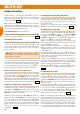
27. Installing the fuselage in-ll piece (wheel well)
If you don’t wish to t a retractable wheel, t the fuselage in-ll piece
in the wheel well from the inside of the fuselage, and secure it with a few
spots of glue. This temporary xing enables you to install a retract unit
subsequently if you wish.
The in-ll piece is also held in place with the self-adhesive landing skid
, which is applied to the underside of the fuselage later.
Fig. 19
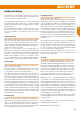
28. Fitting the spinner and propeller
The rst step here is to attach the folding propeller blades
(included
in the power set # 1-01183 or one pair of 11 x 7” blades # 1-00106
for a 3S battery, or separately # 1-00106, or one pair of 8 x 6” blades
#1-01970 for a 4S battery) to the propeller hub
using the socket-
head cap screws
(M3 x 20 mm) and self-locking nuts
.
Tighten the screws just to the point where the propeller blades swivel
back smoothly, but without any lost motion; you may need to adjust the
propeller hub slightly to achieve this.
Slip the propeller hub assembly onto the taper collet
as shown in the
illustration. The whole as-sembly can now be tted onto the motor shaft,
ensuring that there is about 1 mm clearance between the hub backplate
and the fuselage nose.
First t the hub washer, followed by the washer
, the shakeproof
washer
and the M8 nut
, tightening the nut fully. Check carefully
that the clearance between the hub backplate and the fuse-lage does not
change when you tighten the nut!
The purpose of the O-ring
is to ensure that the propeller blades fold
back reliably - this is a par-ticular advantage when you are transporting
the model. The O-ring ts in the notches in front of the spinner backplate,
and wraps round the propeller retaining screw heads and nuts.
Install the spinner
using the M2.5 x 12 mm screw
; check that
the O-ring does not become ‘caught’; it should t in the small recesses.
Fig. 20
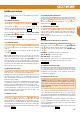
29. Completing the clear canopy
For an even more attractive semi-scale look we recommend painting the
canopy frame
. For best results we suggest using EC
®
COLOR paints.
For example, you could paint the frame, the instru-ment binnacle and the
seat using grey # 60 2806. Allow the paint to dry, then apply the sticker
to form the instrument panel. Glue the seat in place, taking care to
position it accurately.
Glue the two latch tongues
in the slots in the canopy frame, with
the last ridges ush. This is accomplished by applying a little cyano glue
to the slots and the tongues, and then pushing the latch tongues into
place. Check that the latches are parallel and set at right-angles in their
recesses; this ensures that they engage snugly in the latches on both
sides of the fuselage, and retain the canopy securely.
Fig. 21
With the canopy frame tted to the fuselage, the clear canopy
should
be attached to the frame us-ing an adhesive such as clear contact cement.
If using contact adhesive, do not allow it to air-dry in the usual way before
joining; instead apply the glue and immediately place the canopy over the
frame and tape the parts together. Allow the adhesive plenty of time to
set. Be sparing with the glue to avoid sticking the canopy to the fuselage.
It is a good idea to place thin plastic lm between the fuselage and the
canopy frame beforehand. The nal stage is to apply coloured tape all
EN