
Instructions
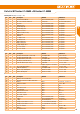

23
Building instructions
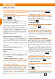
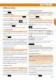
11. Rudder hinges
Glue the three knuckle hinge lugs
(pivots) in the right-hand fuselage
shell.
Fig. 7
12. Installing the tailwheel
Fit the tailwheel
, the tailwheel axle
and two plastic washers
in
the tailwheel holder
. Apply a little hot-melt adhesive on both outside
ends of the axle to prevent it slipping out. Remove any excess hot-melt
glue before gluing this assembly in the right-hand fuselage shell.
Fig. 8
13. Preparing the elevator and rudder servos
The rst step here is to centre the two servos (elevator and rudder) from
the transmitter (or use a servo tester # 1-1359), and t the output arms
on the servo shafts at right-angles (90°) to the servo case.
Caution: If you rotate the servo output lever through 180°, it will not
be at exactly the same angle due to the odd number of splines on the
servo shaft. To avoid problems, start by setting the output arms in the
optimum orientation, and only then cut off the unwanted arms to form
a mirror-image pair.
14. Shortening the servo output arms (elevator and rudder)
The unwanted arm on one side of both servos has to be removed; the
easiest way to do this is to use small side-cutters. Place the servos side-
by-side, and cut off the left-hand lever on one, the right-hand lever on
the other, cutting them off ush with the central boss. Only the innermost
hole is needed for the elevator servo, so the output arm can be shortened
further on that servo.
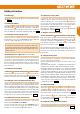
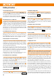
15. Installing the elevator linkage
Screw the clevis
onto the wire elevator pushrod
, and set the distance
between the linkage points to about 136 mm. Slip the pre-formed end of the
pushrod through the guide in the tailplane mount
. Connect the clevis to
the innermost hole in the elevator servo output arm.
Figs. 9 + 10
16. Installing the servos in the right-hand fuselage shell
The two servos should be tted in the recesses in the right-hand fuselage
shell from the inside, gluing them in place virtually ush with the outside.
This is accomplished by applying small spots of hot-melt adhesive to the
servo mounting lugs and pushing them into place; ideally the glue will be
squeezed into the holes in the mounting lugs to provide a mechanical ‘key’
for the servos. If a repair is required, the glue can be cut through from the
outside using a thin-bladed knife, and the servo pushed or tapped out
through the hole in the foam of the left-hand fuselage shell.
Fig. 11
17. Installing and securing the extension leads
Connect the elevator and rudder servo leads to the 1000 mm extension
leads (included in # 1-01286 and # 1-01288).
Secure the connections with connector locks (optional # 1-00137, pack of 5).
The leads can now be deployed in the cable channels, and then on
through the 20 mm Ø fuselage tube
towards the nose.
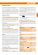
18. Preparing the connector holder
Locate the two cable looms in the fuselage (both leads are the same
length) and allow the ange of the green connector to snap into the
internal securing lugs of the connector holder halves
. Working from
the rear (cable side), apply hot-melt adhesive to the connectors where
they mate with the connector holders, then press each assembly together
fully; hold them straight until the glue has cooled down and set.
Now rmly press together the two halves of the holder
until all the
latching lugs have engaged.
Fig. 12
19. Gluing the connector holder in place
Glue the connector holder
in the appropriate recess in the right-
hand fuselage shell. Locate the cables below the holder and route them
forward, xing them to the right-hand fuselage shell with a cable-tie
through the opening in the rectangular GRP rod
, together with the
leads exiting the fuselage tube. Use a further cable-tie to bundle all the
wires together between these points.
Fig. 12
Before joining the two fuselage shells permanently, please check one last
time that you have installed everything correctly, and that all cables are
secured in such a way that they cannot disturb the joint between the
fuselage shells.
20. Joining the fuselage shells
Please take particular care over this step, as it plays an important part in
the successful completion of the model.
Working carefully and gently, sand all the joint surfaces using 320-grit
abrasive paper.
Now join the fuselage shells ‘dry’ - i.e. without glue: they should t together
snugly, without re-quiring force. Make any minor adjustments required.
Apply thick Zacki Elapor to the joint surfaces of one fuselage shell, leaving
a small gap between the line of adhesive and the outside edge. Be very
careful to avoid glue running into the elevator push-rod opening. Working
briskly, join the shells and check immediately that the fuselage is perfectly
straight, and that everything is aligned correctly. Hold the shells pressed
together lightly for a few minutes, taking care to keep everything straight.
Please don’t try bending the fuselage at this juncture to see if the joint is
strong, as the cyano-acrylate adhesive does not achieve full strength until
several hours have passed.
Fig. 13
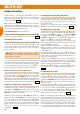
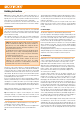
21. Completing the rudder
Glue the three knuckle hinges (pivots)
in the rudder
. The rudder
stiffening tube
(200 mm) should be glued in place adjacent to them,
after which the rudder cover
can be glued in place, applying adhesive
all
round the joint. Take care that no glue runs onto the hinge pivots.
Fig. 14
Glue the rudder horn
in place, angled forward as shown. Fit the
socket-head grubscrew
in the barrel connector
, and install it in
the outer holes of the horn.
Fig. 16
22. Installing the rudder, connecting the pushrod
Position the rudder with the hinge pivots exactly in line with the hinge lugs,
and push them rmly from the rear until they snap into place.
Fig. 15
EN