
Instructions


22
Building instructions
Note: remove the picture pages from the centre of the building instructions!
1. Before you start construction
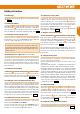
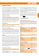
Please check the contents of your kit.
You will nd
Figs. 1 + 2
and the Parts List helpful here.
Notes on recommended accessories:
Electric version with power system / Glider version
The optimum power system for the electric version of the model is the
“LENTUS” brushless power set # 1-01183.
The components of the power set are carefully matched to each other and
fully tested. If you wish to use different batteries, speed controllers, motors
or radio control system components, you do so at your own discretion.
However, if you do this we are unable to provide after-sales service.
Alternatively you may prefer to complete the model as a pure glider. This simply
involves gluing the optional glider nose # 22 4350 to the front of the fuselage.
In this guise the model has a more convincing semi-scale appearance.
The glider version can also be launched by aero-tow if the tow-release
unit # 72 3470 is installed. This is actuated by a length of 1 mm Ø steel
wire running in a 3/2 mm ‘snake’ sleeve.
Electrical connections to the wing-mounted servos
A ready-made (soldered) cable set terminating in green MPX M6 high-
current connectors is available under Order No. # 1-01286 (or with all
servos: Order No. # 1-01288). The set includes the servo extension leads
and all items required to complete the electrical connections at the fuselage.
The servos are connected automatically when the model is assembled,
i.e. the servo leads connect to the sockets in the fuselage when the wings
are slid into place.
This makes it very easy and quick to assemble the model, and enhances
safety by avoiding the danger of mixing up the connectors.
Optional retractable wheel
The Lentus is prepared for installation of the optional retractable wheel
# 1-01759.
With the retract tted, the model is capable of scale FES take-off (Front
Electric Self-launch) from the ground using the same motor and speed
controller. However, it requires the 4S battery # 1-01025 and the smaller
8 x 6” propeller # 1-01970.
2. Cutting the stiffening longerons (GRP rod) to length
Use a pair of side-cutters to cut the shorter GRP fuselage stiffener rod
(2
mm Ø x 700 mm) into two pieces of equal 330 mm length (=> 2 x 330 mm).
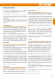
3. Gluing the fuselage stiffeners in place
This is the procedure: rst apply a little Zacki ELAPOR
®
in the channels,
then press the stiffeners into place using a tool such as a screwdriver.
Now run more Zacki ELAPOR
®
along the full length of the stiffeners.
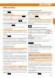
Start by gluing the two prepared fuselage stiffeners
(330 mm) in the
internal channels at the front of the fuselage shells
and
.
Locate the GRP rod
(800 x 2 mm Ø) and glue it in the rear of the
right-hand fuselage shell
. It ts in the upper channel in the fuselage
turtle deck.
Glue the two rectangular-section GRP rods
(5.5 x 3.5 x 250 mm) in
the centre channel in the fuselage shells
+
.
Figs. 3 + 4
4. Mounting the speed controller (cable-tie holders)
Glue the two cable-tie holders
in the recesses in the right-hand
fuselage shell
. Take care to apply the adhesive in such a way that it
cannot run to the outside through the openings.
At a later stage the speed controller is attached to the fuselage side using
the two cable-ties
.
Fig. 4
5. Installing the latch catches
Glue the latch catches
in the appropriate recesses in the right and left
fuselage shells
and
.
Fig. 5
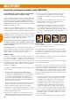
6. Installing the front fuselage reinforcing tube
The front lower section of the fuselage is reinforced with the rectangular-
section GRP tube
, which runs from the motor bulkhead
to the
undercarriage well. The optional retractable under-carriage # 1-01759
is xed to this tube, so it is essential that it is glued very securely to
the foam. Mark the depth to which the tube is inserted into the motor
bulkhead: about 15 mm.
7. Gluing the motor bulkhead to the rectangular tube
Tip: we recommend that you screw the motor (power set # 1-01183) to
the motor bulkhead at this early stage, as it makes handling easier.
Note that the motor cables must be located at bottom right, as seen from the tail.
Apply thick Zacki ELAPOR
®
to all the joint surfaces of the motor bulkhead
and the reinforcing tube
where it ts in the right-hand fuselage
shell. Apply glue to one end of the reinforcing tube, push it into the
rectangular opening in the motor bulkhead as far as the marked point,
then
- working briskly - press this whole assembly into the right-hand fuselage
shell. Ensure that the tube and the motor bulkhead make full contact with
the foam. Apply a little additional hot-melt adhesive to the transition point
between the rectangular tube and the motor bulkhead.
Fig. 5
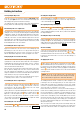
8. Installing the rear fuselage reinforcing tube
Fit the n former
onto the GRP tube
(20 mm Ø x 750 mm), and
glue this assembly securely in the right-hand fuselage shell, taking care
to keep the fuselage straight, i.e. not twisted.
Fig. 6
9. Installing the tailplane mount
Press the two M5 nuts
into the cylindrical screw guides of the
tailplane mount
.
Glue the tailplane mount assembly in the recess in the right-hand fuselage
shell
.
Fig. 6
10. Fin reinforcement
Glue a CFRP strip
(3 x 1 x 120 mm) in the internal channel in both
sides of the n (left and right fuselage shells), then apply a drop of hot-
melt glue to the ends to ll the round recesses.
Fig. 7
EN