4CH H.
This symbol is intended to alert the user to the presence of unprotected “Dangerous voltage" within the product's enclosure that may be strong enough to cause a risk of electric shock. This symbol is intended to alert the user to the presence of important operating and maintenance (servicing) instructions in the literature accompanying the appliance. WARNING TO REDUCE THE RISK OF FIRE OR ELECTRIC SHOCK, DO NOT EXPOSE THIS APPLIANCE TO RAIN OR MOISTURE.
All the safety and operating instructions must be read before the unit is operated. • Make sure to switch the power off before you install the DVR. • There is the danger of an electric shock if the DVR is opened by an unqualified service engineer or installer. • Avoid using the DVR outside of the reference temperature and humidity indicated in the specification. • Avoid exposing the DVR to violent movement or vibration. • Do not use or store the DVR in direct sunlight or near to any source of heat.
TABLE OF CONTENTS Chapter 1 FEATURES .........................................................................................................1 Chapter 2 MAIN MENU OPERATION..................................................................................2 2.1 Quick Setup ............................................................................................................2 2.2 Network Remote Instructions..................................................................................4 2.
Chapter 1 FEATURES Two USB ports (for mouse usage and backup). Dual streaming enhances the speed of network transmission Built-in VGA output up to 1024x768 resolution Individual setup of resolution, frame rate and video quality for each channel Still image snapshot AVI converter with time stamp H.
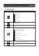
Chapter 2 MAIN MENU OPERATION 2.1 Quick Setup Graphic Icons Resting the cursor on this icon will bring up the four (Main Menu/ Search/ Backup/ PTZ) menu icons. MAIN MENU. SEARCH SETUP. BACKUP. PTZ CONTROL. Turn On/Off recording. PLAYBACK Resting the cursor on this icon will bring up five (PAUSE/ PIP/ ZOOM/ AUTO SEQ/ LOCK) display icons. PAUSE, to pause LIVE image PIP, picture in picture ZOOM, zoom in / out the screen size AUTO-sequence LOCK, activate the key lock.
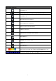
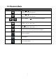
GUI Hints and Tips Recording is on Number represents the current selected LIVE audio channel Live Audio is off Motion detected on the channel Sensor triggered on the channel Video loss detected on the channel USB device detected DVR has been connected onto the Internet.
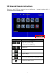
2.2 Network Remote Instructions Same user and DVR-site interface, the only difference is network toolbar which is situated on the lower bottom right. Icon / Description Low Video Quality (LQ) High Video Quality (HQ) * Please refet to 4.7.
2.
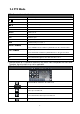
2.4 PTZ Mode PTZ – Remote Controller Control / SLOW Move PTZ up. / Move PTZ down. / Move PTZ to the left. / Move PTZ to the right. ZOOM + PTZ zoom-in. ZOOM - PTZ zoom-out. FOCUS + PTZ focus-in. FOCUS - PTZ focus-out. IRIS + PTZ iris-open. IRIS - PTZ iris-close. TOUR Activate PTZ pre-set tour. PRESET + NUMBER PLAY + NUMBER ZOOM PIP FREEZE * To save a preset location Press PRESET and a number key. DVR will save the current location.
Same as [PIP]. Set current PTZ location as the starting point of the line-scan. Same as [FREEZE]. Activate line-scan. Same as [ZOOM]. Set current PTZ location as the ending point of the line-scan. To move PTZ in 360° PTZ zoom in or PTZ zoom out. PTZ focus in or PTZ focus out. PTZ IRIS open or PTZ IRIS closes. Below functions needs support from specific PTZ. Please check the user manual of your PTZ manufacturer for detail. AUX 1~8. [AUTO] +「1」~ +「8」 [Backup] icon, click to customized function.
Chapter 3 INSTALLATION 3.
3.2 Hard Disk Installation Step 1: Remove the 3 screws from DVR as cycled below (PIC 1). (PIC 1) Step 2: Remove the front cover from DVR as indicated by the arrow (PIC 2).
Step 3: Place the HDD on the HDD plate and connect the power and the SATA cables (PIC 3). (PIC 3) Step 4: Screw the bottom of the DVR as indicated as cycled (PIC 4).
Chapter 4 BASIC OPERATION and MENU SETUP 4.1 Main Menu Setup To enter the main menu and setup the DVR, please log-in account and enter user password. The default password of the administrator is “123456”. Please refer to “Account Setup” for related setup of other log-in users. Main Menu – Mouse Control (Right mouse click to enter Quick Setup Menu) Switch between capital and small letters. / Switch between numbers and letters. Press to cancel the setup, and re-choose the login account.
Main Menu – Remote Control ler and Front Pannel Control (Click MENU button to enter Quick Setup Menu ) Switch to different options under one item Switch to different items MENU ESC ESC ENTER Press to confirm setup (OK) Press to cancel setup (CANCEL) Enter the menu, or display virtual keyboard 4.
Item Description Select STOP to stop recording or OVERWRITE to reuse the HDD when HDD is full. HDD FULL [Stop]:Stop Recording [Overwrite]:Start to overwrite beginning from the oldest data of HDD, and continue to record. OSD Position X Set time stamp of OSD position X OSD Position Y Set time stamp of OSD position Y OSD Position Setup Video Preservation (Hours) Quality & Frame Rate Setup… OSD position time stamp setup Information stored within the HDD is preserved for only a specified length of time.
4.3 Event Setup Item Description Motion Setup Enter to set up motion detection Sensor Setup Enter to set up sensor detection 4.3.
Item Alarm Duration(Seconds) Motion Popup Enable Sensitivity Motion Area Setup Description Alarm duration time (1~60 seconds). Check the box to Enable/ Disable popup screen function for all channels. When motion is detected in LIVE mode, the detected channel image will popup in full screen display. Check the box to Enable/ Disable motion detection for each channel. Drag the bar or press ◀ ▶ to set up Sensitivity from value 0 to 10 for each channel.
4.3.2 Sensor Setup Item Alarm Duration(Seconds) Sensor Popup Description Alarm duration time (1~60 seconds). Check the box to Enable/Disable popup screen function for all channels. When Sensor is detected in LIVE mode, the detected channel image will pop up in full screen display. Sensor Polarity Click or press ▼ to select between HIGH/ LOW voltage for triggering sensor detection or OFF to turn off polarity for each channel Low Polarity:Sensor has not been triggered.
4.4 Schedule Setup Apart from manual recording, you can also setup the recording time by weeks and schedule recordings include: normal, motion detection, and sensor detection. Item Page Holiday Setup View Event Setup Description Click or press ▼ to select Page. Each page provides 10 schedules for setup. 5 pages in total. Enter to setup holiday, maximum up to 50 days. View Normal/ Motion / Sensor Setup. 4.4.1 Schdule Record Setup Click on the time icon on the left side. The setup menu will be displayed.
Item Enable Schedule Record Enable Schedule Motion Detect Enable Schedule Sensor Trigger Description Enables schedule recording according to the time schedule (shown below). Enables schedule motion detection recording according to the time schedule (shown below). Enables schedule sensor trigger recording according to the time schedule (shown below). 4.4.2 Holiday Setup Since holidays are different between countries and regions, you can setup the holiday of your location accordingly (Maximum Setup: 50).
Item Description Mask Check the box to Enable/ Disable mask function for LIVE mode Drag the white bar or press ◀ ▶ to adjust Sharpness of your camera from value 0 to 15. The default value is 1. Drag the white bar or press ◀ ▶ to adjust Brightness of your camera from value 0 to 255. The default value is 128. Drag the white bar or press ◀ ▶ to adjust Contrast of your camera from value 0 to 255. The default value is 100.
4.6.1 Permission Setup The Account Setup is set to provide individual user (maximum of 4 users) role-based permissions, including access to Setup menu, Network operation, PTZ function, Playback, Utility, Backup and Mask on specific channels while playing back. 4.
Item Connect type Description Setup mode for network connection: ADSL、 、DHCP、LAN. HTTP Setup Enter to set up HTTP for remote access into DVR. DDNS Setup Enter to Enable/ Disable DDNS function and set up. Mail Setup Enter to Enable/ Disable Email notification and setup. 4.7.1 Networking Setup The DVR supports DHCP, LAN and ADSL access for network connection. 4.7.1.1 DHCP If the DHCP option is used for DVR network connection, an IP address is assigned by the DHCP server automatically.
4.7.1.2 LAN Select LAN for network connection, the following information is required. Item IP Address Subnet Mask Gateway DNS Description Enter IP address provided by ISP Enter IP address of Subnet Mask provided by ISP Enter IP address of Gate way provided by ISP Enter DNS address provided by ISP. (Note: The correct DNS address must be entered for DDNS function).
4.7.1.3 ADSL Select ADSL for network connection, the following information is required.
4.7.2 HTTP Setup Item Description Enable HTTP Server Check to enable HTTP server. Users can remotely access into the DVR over the network if the HTTP function is activated. Enter a valid port value from 1 up to 65535. The default value is 80. Port Quality and Frame Rate Setup for Network Transmission No. Quality Check to activate the transmission of each camera. Choose from Below Basic / Basic/ Normal/ High/ Highest. FPS Choose recording frame rate (1~30FPS).
4.7.3 DDNS Setup Item Description Enable DDNS Check/ Uncheck to Enable/ Disable DDNS function. DDNS Server Select the DDNS Server wanted. Host Name Enter the registered hostname. User Name Enter user name. Password Enter password. 4.7.
E-mail can be used as a form of notification when an event occurs (VLOSS, MOTION, and SENSOR). Item Enable E-mail Notification SMTP Server Description Check the box to enable/disable E-mail Notification function. Enter to set up SMTP Server name. User Name Enter to set up User Name. Password Enter to set up Password. Sender E-mail Trigger Event Receiver E-mail Enter to set up e-mail address of sender.
4.8 PTZ & RS-485 Setup The DVR allows users to control PTZ functions of your camera. To enable PTZ function, the 485 cable should be connected to the RS-485 port of DVR. Item Enable PTZ Protocol PTZ ID Baud Rate Description Click the box to Enable/Disable PTZ function for each channel. Set up the protocol of PTZ cam. Click or press ◀ ▶ to set up PTZ ID. The valid ID value is from 1 to 64. Select Baud Rate for PTZ from 2400、4800、9600 、19200 RS-485 ID RS-485 Baud Rate Reserved.
4.9 System Setup Item Description DVR Name The name of DVR will be shown when users login from remote access. DVR Location The location of DVR will be shown when users login from remote access Language Auto-Seq Interval ( Seconds) Remote ID Click or press ▼ to select OSD language. Click or press ◀ ▶ to set up duration time in seconds for the interval between channels under Auto-Seq mode. Preserved Function. After one minute without any action, the DVR will switch to LIVE mode automatically.
4.9.1 Display Setup Item Description Auto-Seq Interval ( Seconds) Click or press ◀ ▶ to set up duration time in seconds for the interval between channels under Auto-Seq mode (1~999 seconds). Show OSD Show DVR Status Turn On / Off OSD display Turn On / Off DVR illustration and record status display Show Date/Time Turn On / Off date and time display Show Channel Name Turn On / Off channel name display CRT Make the display more suitable for CRT monitor.
4.9.2 Date/ Time Setup Item Description Hour Format 12HOURS/ 24HOURS Date Format MM-DD-YY/DD-MM-YY/YY-MM-DD Date/Time Position Change Date & Time Time Zone Setup Internet Time Setup Choose the position of Time and Date display Setup time and date of DVR Set up GMT and Daylight Saving Time. Setup automatic synchronization with internet server 4.9.2.1 Change Date & Time Users are allowed to setup date and time of the DVR.
4.9.2.2 Time Zone Setup In time zone setup, users can change the time zone and activate Daylight Saving Time function according to your DVR location. Item Select Time Zone Daylight Saving Time Description Enter to modify GMT from GMT- 13 to GMT+ 13 Turn On/ Off Daylight Saving Time 4.9.2.3 Internet Time Setup Synchronize your DVR time with internet time server.
Item Description Check to enable DVR automatic synchronization function. Select this Automatic Synchronization option to enable the function, DVR will automatically synchronize the time upon rebooting or by every 24 hours after booting. Update Now Date and Time show on DVR will immediately correspond with those in internet server. 4.9.
Item Mouse Speed Description Adjust the mouse moving speed Buzzer & Relay Setup Key Tone Enable/ Disable keystrokes. ALARM BUZZER Enable/ Disable buzzer operation when the alarm is triggered for HDD error, sensor, motion and vloss (Video Loss). ALARM RELAY Enable/ Disable the signal to be sent to the RELAY OUT blocks when the alarm is triggered for HDD error, sensor, motion and vloss. 4.9.
4.10 Utility Setup Item HDD Initialization USB Initialization System Recovery Reset System Events Copy Setup to USB Download Setup from USB Upgrade Description Select to enter hard disk initialization menu. Please stop recording before entering this menu. Enter the menu, system will show all the data (model/ volume) of HDD that is installed in the DVR. Check the HDD you’d like to initialize, then press “Start”. HDD initialization is successful when the status shows “Succeed”. Clean up all data on USB.
4.11 Diagnostic Item Version IP Address MAC Address HDD Volume HDD Used Rate HDD Status Format Time Description The current firmware version of DVR The connected IP address of DVR. If disconnected from network, the screen will display” NETWORK DISCONNECT”. MAC Address of DVR The capacity of HDD Percentage of space used on HDD. Shows HDD status. USING means the HDD is now used for recording. GOOD/ BAD means the HDD has a known/ unknown format for the DVR.
Chapter 5 SEARCH & BACKUP 5.1 Search Setup Item Description Event Search Press to enter event search menu. Time Search Press to enter time search menu. 5.1.
The DVR automatically records events with type, time and channel information included. If there is recording data for an event, a yellow signal icon will be shown on the left side of time information. Rest your cursor under the line and press “enter”, or left click your mouse to playback the recording data. Item Criteria Page Date/Time Description Setup conditions of the event search function Convert pages of events Date/ time when the event occurred.
The amount of events can be numerous. Therefore, you can facilitate event sorting by setting up “criteria”. Setup “start time” and “end time” for each event search, then the search result will be limited to this specific period of time. Only events and channels that are checked will be sorted in event search as well. 5.1.2 Time Search TIME SEARCH, you can search for a specific time of the recording data to playback. Dates with recording are shown by data marked with a red square [ □ ].
Click “date” to display recording time of that specific date with time bar. You can change time (hour/ minute/ second) or click on a specific time of time bar by mouse then press “YES”. DVR will playback the selected recording data. 5.2 Backup Setup User can back-up any segment of recorded data in a specified time frame. To do so, connect a USB flash driver to the DVR. The format of backup file is IRF file and a file player is also saved in the USB driver.
Chapter 6 SPECIFICATION I/O Video System NTSC / PAL switch Video Input 4CH BNC Video Input Level 1.0 Vp-p Composite, 75 Ohm Balanced Video Output 1CH BNC SPOT Output 1CH BNC VGA Output 1024x768 Audio Input 1CH RCA Audio Input Level 0.5~1.4 Vp-p @ 20K Ohm Audio Output 1CH RCA Audio Backup YES Sensor 4 input / 1 output RS-485 Pan / Tilt / Zoom camera USB Port 2 ports Mouse USB mouse IR Remote Controller YES STORAGE SATA HDD x1 (Max.
Post-Alarm 1-60 sec Recording Motion Detection 22X18 (sensitivity 0~10) PLAYBACK Time, Event Search Mode fast forward/backward 2X/4X/8X/16X/32X/64X Playback Speed slow forward/backward 1/2X,1/4X,1/8X,1/16X play/pause Backup Mode USB flash driver / Network NETWORK Network H.
Chapter 7 NETWORK SURVEILLANCE 7.1 Remote Connection Step 1:Enter the IP address of the DVR in the IE browser. Provides two different ways of DVR connection, one is the use the Internet Explorer; the other to download and install the software to the PC. Step 2: A window will pop-up. Please enter the user name and password. Default user name is admin and password is 123456. Other related setup about user account and password, please refer to section on “Account Setup“.
Step 3: You’ve logged into the DVR Internet Explorer Software Application 43