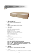
50 4CH 16CH / 8CH / 4CH 16CH / 8CH / 4CH BuiltBuilt-in DVDDVD-RW Writer or CDCD-RW Writer User’s Manual Please read instructions thoroughly before operation and retain it for future reference. MPEG4 DVR SERIES_V0.
IMPORTANT SAFEGUARD CAUTION RISK OF ELECTRIC SHOCK CAUTION: To reduce the risk of electric shock, do not expose this apparatus to rain or moisture. Only operate this apparatus from the type of power source indicated on the label. The lightning flash with arrowhead symbol, within an equilateral triangle, is intended to alert the user to the presence of uninsulated “dangerous voltage” within the product’s enclosure that may be of sufficient magnitude to constitute a risk of electric shock to persons.
TABLE OF CONTENTS PARTS AND FEATURES 1.1 1.2 1.3 1.4 1.
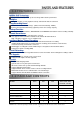
PARTS AND FEATURES 1.1 FEATURES MPEG4 DVR Technology Compression format provides crystal clear image with real time performance Multiplex Allows live display, record, playback, backup, and network all at the same time LongLong-Recording Hours: 500GB can record more than 4 days.
1.
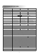
MODEL 8CH / 8CH (D) 16CH / 16CH (D) 4CH / 4CH (D) Specification Continued … Support up to 6 letters Camera Title Video Adjustable Date Display Format Hue/Color/Contrast/ Brightness YY/MM/DD, DD/MM/YY, MM/DD/YY, and Off Daylight Saving Yes Power Source Power Consumption DC 19V <64 W Operating Temperature Dimensions (mm) System Recovery Optional Peripherals 4CH: <42 W ; 4CH (D): <64 W 10℃ ~ 40℃ (50℉~104℉) 432mm (W) × 90mm (H) × 326mm (D) 432mm (W) × 90mm (H) × 326mm (D) System auto recovery
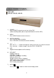
1.4 FRONT PANEL 16CH / 8CH 16CH (D) / 8CH (D) / 4CH (D) 1) POWER: Press “POWER” button to turn on/ turn off the DVR. (Under recording mode, please stop record before turn off the DVR) 2) MENU: Press “MENU” button to enter main menu. 3) ENTER / RECORD: Press “ENTER” button to confirm. Press “RECORD” to activate the manual recording. 4) “+ “ “ - ” : Press “+ “ or “ - ” button to change the setting in the menu / to select the channel. Press “+“ and “- -” buttons to open / close the DVD / CD WRITER.
) 9) “ ”: Press “ ” button to pause the play back files. “ ”: Press “ ” button to stop the play back files. 10) “ “: Under playback mode, press “ ” button to fast rewind. 11) “ “: Under playback mode, press “ ” to fast forward. 12) “ZOOM” : Press “ZOOM” button to enlarge the picture of selected channel (2X digital zoom). 13) “PLAY” : Press “PLAY” button to playback recorded files. 14) “▲▼◄►“ : Press “▲▼◄►” to move the cursor up / down / left / right.
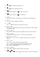
1.4 FRONT PANEL Continued… Continued… 4CH 1) “HDD Cartridge Lock” : Lock / Unlock the cartridge of the HDD. 2) “USB” : Support firmware update and files backup. 3) “LED LIGHT” : HDD: HDD is reading or recording HDD Full: HDD is full. ALARM: Once the alarm is triggered TIMER: When timer recording is turned on PLAY: Under playing status REC: Under recording status 4) “MENU” : Press “MENU” button to enter main menu. 5) “ENTER” / “SET” : Press “ENTER” button to confirm.
7) “ZOOM ” : Press “ZOOM” button to enlarge the picture of selected channel (2X digital zoom). 8) “ ”/“-”: Press “ “ button to show the 4 channel display mode. Press “ - ” button to change the setting in the menu. 9) “SEQ” / “ + ” : Press “SEQ” button to activate the call monitor function and press “SEQ” button again to escape the call monitor mode. Press “+ ” button to change the setting in the menu. 10) “POWER” : Press this button to turn on / turn off the DVR.
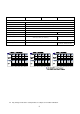
1.5 REAR PANEL 14 16CH / 16CH (D) 13 12 1 2 3 4 5 6 7 8 9 16 15 10 11 12 13 14 15 16 17 MONITOR LOOP INPUT 1 75? 8 9 HI-IMPEDANCE 16 75? 3 2 4 HI-IMPEDANCE RS 485 DISKARRAY CALL 1 EXTERNAL I/O IR LAN D/V USB LINK ACT.
1) DISK ARRAY PORT: Connect to disk array for extend HDD capacity. 2) IR: Connect to IR receiver. 3) RS485: 1234 Connect to external device (such as PTZ camera) with RS485-A and RS485-B. 4) EXTERNAL I/O PORT: Connect to external device. Control external device or get controlled remotely by external device (alarm input, external alarm, PTZ camera). 5) USB PORT: Support firmware update and files backup. 6) D/V PORT (Digital Video Port): Connect to VGA connector card.
GETTING STARTED 2.1 GETTING STARTED Connecting all the devices to construct a surveillance. NOTE: Please refer to Appendix #1 for HDD installation instructions. NOTE: Please refer to “Section 1.5 Rear Panel” for connection. NOTE: Please refer to Appendix#2 for pin configurations of the external I/O port . 1) Install HDD: The HDD must be installed before the DVR is turned on. 2) Connect cameras. 3) Connect monitors. 4) Connect the external devices.
BASIC OPERATION 3.1 RECORDING The DVR offers three recording modes, manual record, event recording, and timer record. If power is off accidentally, recorded video files will still be stored in the HDDs. DVR will return to original recording status after power is on again. 1) MANUAL RECORDING (continuous recording) : Recording is initiated by manually pressing the “REC” button.
3.2 PLAYBACK 16CH / 8CH 16CH (D) / 8CH (D) / 4CH (D) Press “ PLAY ” button, the DVR will display the last recording video. 1) FAST FORWARD (F.F. ) & FAST REWIND (REW): You can increase speed for fast forward and rewind on the DVR. In the playback mode, * Press ” ” once to get 4X speed forward and press twice to get 8X speed,… and the maximum speed can reach 32X. * Press ” ” once to get 4X speed rewind and press twice to get 8X speed, … and the maximum speed can reach 32X.
4CH Press “ PLAY ” button, the DVR will display the last recording video. 1) FAST FORWARD (F.F. ) & FAST REWIND (REW): You can increase speed for fast forward and rewind on the DVR. In the playback mode, * Press “ “ once to get 4X speed forward and press twice to get 8X speed, … and the maximum speed can reach 32X. * Press “ “ once to get 4X speed rewind and press twice to get 8X speed, … and the maximum speed can reach 32X. * The type of recording image size (Frame or CIF )will also shown on the screen.
DETAILED MENU CONFIGURATION 4.
4.2 MAIN MENU OPTIONS___RECORD Press “MENU” button to enter the main menu list. The default admin password is 0000. Enter the default password and press “ENTER”. (Users could alter the password later, please refer to “Section 4.11 ADVANCE MENU_SYSTEM”) Move the cursor to the “RECORD”, and press ”ENTER”, then the screen will show the following options.
8) EVENT RECORD IPS: Recording is activated by event (alarm and motion trigger). Select the images per second for event record, The options are as the followings: NTSC: PAL: NTSC FRAME: 120, 60, 30, 15 PAL FRAME: 100, 50, 25, 12 CIF: 480, 240, 120, 60 CIF: 400, 200, 100, 50 9) TIMER RECORD IPS: Recording is activated by timer schedule.
1) DATE: A scheduled record date (SUN/MON/TUE/ WED/ THU/ FRI/ SAT/ MON–FRI / SATSUN / DAILY/OFF) could be set to activate the timer recording. NOTE 1 : Specific date could be changed by “+” or “-” button. NOTE 2 : If you plan to set the timer recording across the midnight, there are two ways for setting the timer recording schedule, please following the instructions below.
4.5 MAIN MENU OPTIONS___ADVANCE ADVANCE CAMERA DETECTION DISPLAY ALERT REMOTE SYSTEM NETWORK BACKUP HDD INFO EVENT LOG (MENU) RECORD TIMER DATE ► ADVANCE Move the cursor to the “ADVANCE”, and press ”ENTER”, then the screen will show the following options. 4.6 ADVANCE MENU ___CAMERA Move the cursor to the “CAMERA”, and press ”ENTER”, then the screen will show the following options.
4.7 ADVANCE MENU ___DETECTION Move the cursor to the “DETECTION”, and press ”ENTER”, then the screen will show the following options.
▲▼◄►: navigates between targets. d) LS : The sensitivity of comparing two different images. The smaller the value is, the higher sensitivity for motion detection. The highest sensitivity setting is 00, the lowest sensitivity setting is 15. The default value is 07. e) SS : The sensitivity towards the size of the triggered object on the screen.(the number of motion detection grids). The smaller the value is, the higher sensitivity for motion detection.
4.8 ADVANCE MENU ___DISPLAY Move the cursor to the “DISPLAY”, and press ”ENTER”, then the screen will show the following options. DISPLAY TITLE DISPLAY DATE DISPLAY HDD INFO LOSS SCREEN PLAYBACK INFO DWELL DURATION (SEC) DE-INTERLACE MONITOR OUT WATERMARK ON ON ON BLUE NORMAL 2 ON MAIN ON 1) TITLE DISPLAY: Turn the channel title display on / off. 2) DATE DISPLAY: Turn the date display on / off. 3) HDD INFO” Turn the display information of internal HDD on / off.
4.9 ADVANCE MENU ___ALERT Move the cursor to the “ALERT”, and press ”ENTER”, then the screen will show the following options. ALERT EXT. ALERT INT. BUZZER KEY BUZZER VLOSS BUZZER MOTION BUZZER ALARM BUZZER HDD BUZZER HDD NEARLY FULL (GB) ALARM DURATION (SEC) PRE-ALARM ON ON ON ON ON ON ON 05 05 OFF 1) EXT. ALERT: Set the sound on / off when external alarm is triggered. 2) INT. BUZZER: Set the sound of KEY / VLOSS / MOTION / ALARM / HDD FULL on or off.
4.10 ADVANCE MENU ___REMOTE Move the cursor to “REMOTE”, and press ”ENTER”, then the screen will show the following options. Take 16CH as an example TITLE 01 02 03 04 05 06 07 08 PREV DEVICE PTZ CAMERA CAMERA CAMERA CAMERA CAMERA CAMERA CAMERA NEXT REMOTE ID 001 002 003 004 005 006 007 008 PROTOCOL P-D NORMAL NORMAL NORMAL NORMAL NORMAL NORMAL NORMAL RATE 02400 02400 02400 02400 02400 02400 02400 02400 1) TITLE: Title of each camera.
4.11 ADVANCE MENU ___SYSTEM Move the cursor to the “SYSTEM”, and press ”ENTER”, then the screen will show the following options. SYSTEM SERIAL TYPE BAUD RATE HOST ID IR PASSWORD RESET DEFAULT CLEAR HDD UPGRADE AUTO KEYLOCK LANGUAGE VERSION VIDEO FORMAT RS - 485 02400 003 ON SETUP RESET MASTER NO NEVER ENGLISH 1042-09-H6-04-AA-08 NTSC 1) SERIAL TYPE: Press “ENTER” or “+” or “-” button to set the control serial type (RS-485, RS-232) of DVR.
4.12 ADVANCE MENU ___NETWORK Move the cursor to the “NETWORK”, and press ”ENTER”, then the screen will show the following options. NETWORK NETWORK TYPE DNS PORT 1) STATIC 168. 95. 0080 1. 1 NETWORK TYPE (STATIC): Select NETWORK TYPE, and press “+” or “-” button to set the network type as STATIC, and then press “ENTER” to go to the submenu of the network. In the submenu of network type, use “+” or “-” button to set all the information needed in the DVR. See the illustration below. STATIC 60. 121. 46.
4.13 ADVANCE MENU ___ BACKUP 16CH / 8CH / 4CH Move the cursor to the “BACKUP”, and press ”ENTER”, then the screen will show the following options. BACKUP USB BACKUP Select “USB BACKUP” and then press “Enter”. USB BACKUP START TIME END TIME AVAILABLE SIZE CHANNEL HDD NUM BACKUP TO USB 2005-12-27 11 : 25 : 46 2005-12-27 11 : 50 : 58 0512 MB 01 MASTER START 1) START TIME: Select the start time of the backup. 2) END TIME: Select the end time of the backup.
16CH (D) / 8CH (D) / 4CH (D) Move the cursor to the “BACKUP”, and press ”ENTER”, then the screen will show the following options. BACKUP USB BACKUP DISK BACKUP Select “DISK BACKUP” and then press “Enter”. DISK BACKUP START TIME END TIME AVAILABLE SIZE CHANNEL HDD NUM BACKUP TO DISK 1) 2005-11-30 15 : 30 : 00 2005-12-01 16 : 00 : 00 4083 MB 01 MASTER START Press “+” and “-” buttons to open the DVD / CD WRITER. Put the DISK into DVD / CD WRITER, and press “+” and “-” buttons again to close.
4.14 ADVANCE MENU ___HDD INFO You can get all the capacity information of the connected HDD. HDD INFO HDD NUM MASTER EXT001 EXT003 EXT005 EXT007 EXT009 EXT011 HDD SIZE 400.517 400.517 400.517 NO HDD NO HDD NO HDD NO HDD HDD NUM SLAVE EXT 002 EXT 004 EXT 006 EXT 008 EXT 010 EXT 012 HDD SIZE NO HDD 400.517 NO HDD NO HDD NO HDD NO HDD NO HDD 4.
5.1 SEARCH ADDITIONAL OPERATION 16CH / 8CH 16CH (D) / 8CH (D) / 4CH (D) Press “ ”+“ ” buttons on the front panel of the DVR to enter the search mode. Then the screen will show the following options. 4CH Press “SEARCH” buttons on the front panel of the DVR to enter the search mode. Then the screen will show the following options. SEARCH HDD FULL RECORD SYSTEM ALARM MOTION EVENT TIME MASTER LIST LIST LIST LIST LIST SEARCH SEARCH 1) HDD: Select the the specific HDD.
5.2 2X DIGITAL ZOOM Press “ZOOM” button on the front panel of the DVR to enlarge the picture of selected channel (2X digital zoom). You will have ¼ view size of the enlarged picture. Therefore use the “ ▲▼◄► “ to navigate. 20052005-MAYMAY-30 [MON] 14:50:37 DIGITAL ZOOM 400 GB 20052005-MAYMAY-30 [MON] 14:50:37 DIGITAL ZOOM 01 400 GB 01 1) Press the “ZOOM” button again to exit the zoom picture. 2) Press “ ▲▼◄► “ button to move the zoom position.
5.5 USB UPGRADE Users can use USB to upgrade. Please format the USB memory device as FAT 32 format first. 1) Get the upgrade files from your distributor. 2) Save the upgrade files in your USB device (Do not change the file name). 3) Go to the “MAIN MENU – SYSTEM - UPGRADE” , and press “ENTER”. 4) Select “YES”, and press “ENTER” again to confirm upgrade.
2) Software Operation: Operation c Connect DVR to PC via RJ45 network line. d LAN Setting : The default DVR IP is “192.168.1.10”, and default “username” and “password” are both “admin”. Users should set PC’s IP address as “IP:192.168.1.XXX XXX (1~255, except 10)” (in order to make the PC and DVR under the same domain). e Double click to enter login page. Key in IP (192.168.1.10), username (admin), password (admin), port (80) in the login page.
i Introduction of Basic Operation : Video Web Server Control Panel. Digital Device Control Panel ~ Take 16CH DVR as an example a c d e b f g h i 60.121.46.236 j. k. l. m. n. o. p. q. r. s. a. Image Transfer Rate Per Second b. Data Transfer Rate c. Connect / Disconnect d. Resolution: NTSC: 320 × 228 PAL: 320 × 276 t. u. v. w. ; 640 × 456 ; 640 × 552 e. Image Quality (High, Medium, Low) f.
g. h. i. j. k. l. m. n. o. p. q. r. s. t. u. Record : press this button to start recording, and press this button again to stop recording. The recorded files will be saved to the designed path on the PC. Each recording file can be up to 18,000 frames. When the recording file is full, the new recorded file will be saved as the second file. If the HDD space is less than 200MB, the program will stop recording. System Config: press this button to enter the setting page of the software AP.
Digital Device Control Panel ~ PTZ 60.121.46.236 219.85.22.168 j. k. l. m. n. j. k. l. m. n. o. p. q. r. o. p. q. r. Preset 1 ~ 16 AUTO Zoom Tele Zoom Wide Focus Near Focus Far Max Zoom In Max Zoom Out Enter PTZ Control On / Off: When PTZ control mode is turned on, users could select the PTZ device, and press “OK” button to enter the PTZ control AP screen.
j Playback Operation AP Playback Window : One click to activate AP Config. Setting Box : • De-interlace • De-blocking • OSD • AVI Convert • Config. Setting • Watermark • Open Previous File • Open Next File A B A. Playback Information : Display information such as “Date”, “Time”, “Resolution”, “ Rewind / Forward Speed”, “Status” and “Functions”, etc.. B. Time Progress Bar : Show the playback progress status. C.
3) Advanced Setting: Setting 60.121.46.236 Press “System Config ” button to enter the system setting page. Network The network configuration allows DVR to be available for Ethernet network or dial-up. c Static IP: Enter the “server IP”, “gateway”, “net mask” and “web port”, then press “APPLY” to confirm. d PPPoE: PPPoE: Enter the “username” and “password” provided by your ISP (Internet Sever ) supplier, then press “APPLY” to confirm.
DDNS c DDNS is a service for transforming dynamic IP to corresponding to a specific “Hostname”. d DDNS Apply: Go to a website which provide free DDNS services and apply a “Hostname”. See the example below. e Enable the DDNS function: function Enter “DDNS username” into “username” column. Enter the “DDNS password” into “password” column. Enter the “Hostname” into “Domain” column. Choose the “DDNS system name”. After setting, press “APPLY” to confirm.
Mail c When alarm or motion is triggered, a video copy file can be captured. DVR can send e-mail notification to the assigned recipients (up to 5 recipients). ***Note***: To activate the e-mail notification function, please enable the function of e-mail notification in the “Alarm” setting first (page 43). d Add the recipients’ email accounts in the “Mail Account” column. The detailed information (SMTP server, username and password) refer to e-mail system supplier.
DVR – Camera Setting Take 16CH as an example c Each camera channel can be adjusted independently. d Select the desired camera channel. Press “Edit Edit” to enter the setting box. e Title: Enter the camera channel name up to 6 characters. f Adjustment: Adjust the BR (brightness) / CT (contrast) / SU (saturation) / HU (hue) / REC (recording) of the camera. g After setting, press “OK” and then press “APPLY” to confirm.
Detection Take 16CH as an example c Select the desired channel, and press “Edit Edit” to enter the motion detection sensitivity and area setting box. d Motion Detection Sensitivity: Sensitivity Set the detection sensitivity in 4 different adjustable factors. LS: The sensitivity of comparing two different images. The smaller the value is, the higher sensitivity for motion detection. SS: The sensitivity towards the size of the triggered object on the screen (the number of motion detection grids).
Network Backup & Playback c d Backup the recorded files to the PC from DVR via network. Enter the backup information Æ Press “Start” Æ Success Æ Covert Æ Play File. 1 2 1. Playback Information 3 (1) De-interlace (2) De-blocking (3) OSD (4) AVI Convert (5) Config. Setting (6) Watermark (7) Open Previous (8) Open Next File 5 4. Playback Control Buttons : Play / Stop / Pause / Fast Rewind / Fast Forward 2. Time Progress Bar 3. Functions : 4 5. Snapshot 6. Close the Player.
Alarm c d e f g Alarm Trigger: Trigger Enable or disable Email and FTP notification function. Alarm Method: Method Two notification methods — Email and / or FTP. Post Number: Number Set MJPEG pictures (1-10 pictures). Alarm Duration: Duration Set the duration time of motion trigger recording (3 sec., 15 sec., 30 sec., 1 min., or 30 min.). Alarm Refresh: Refresh Clean the alarm message “ ” which is shown on the screen.
General c Get the information of DVR firmware version in this window. d Select “Turbo Step” Step” (1 - 10). 10) To speed up menu selecting or the control of the PTZ camera under video web server, users can activate "Turbo" function by clicking this button. Users are allowed to change the turbo steps from 1 to 10. Ex. If the value of turbo step is “5“ means that when user press one of the button up/down/left/right, one click is as clicking 5 times. e Max Log List: List Set the maximum number of log list.
Online User Info c Get all the online users’ information list (Name, IP Address, Authority Level, Resolution and Image Quality). File Path c Snapshot Path: Path Assign the route for saving the snapshot picture. d Record Path: Path Assign the route for saving the manual recording file. e Alarm Audio Path: Path The default alarm audio sound is “alarm.wav”. Users could have their own alarm sound file by giving the file path. 45 Andy 60.121.46.
5.7 CONNECT TO AP VIA IE BROWSER The DVR can be viewed over the network with a web browser. Please install licensed software AP first. *** This function is suitable in both Windows 2000 and Windows XP XP *** Step 1: 1 Type in IP address into the URL address box and press enter. Then you’ll see the following page. Note: If the TCP port number is not 80, see the example below. IP address: 60.121.46.236 ; Port number: 888 Æ Key in “http://60.121.46.236 :888” into the URL address box and press enter.
5.8 GPRS GPRS function Installation and Viewing (Take Motorola 768i for example) 1) Your mobile service provider must have GPRS service, and the phone handset needs to support GPRS and Java MIDP 2.0 to run the application. 2) Connect to the website http://211.22.74.18 via the web browser of your cell phone. (Make sure that your GPRS function is working). 3) Download and install “16CH_MPEG16CH_MPEG-4” / “8CH_MPEG8CH_MPEG-4” / “4CH_MPEG4CH_MPEG-4”.
6.1 FAQ TROUBLE SHOOTING Please refer to the FAQ table below for easy trouble shooting. The table below describes some typical problems and also their solutions. Please check them before calling your DVR dealer. PROBLEM No power SOLUTION Check power cord connection. Confirm that there is power at the outlet. Not working when pressing any button Press any key and then enter the password to exit “Key Lock” mode. Timer record is not working Check if the “RECORD ENABLE” is set to “YES”.
APPENDIX #1 APPENDIX #1 – INSTALL THE HDD 16CH / 8CH 16CH (D) / 8CH (D) / 4CH (D) Carefully following the steps to ensure correct installation. *** Note: If you want to install two HDDs, please set one HDD to “Master Mode” or “Single Mode”, and the other one to “Slave Mode”. *** 1 2 1) Open the upper cover of the DVR and screw out the bracket. 2) Screw HDD to the HDD bracket. 3 ~ 8 3) Connect the HDD to power connector and IDE BUS (make sure to align the HDD precisely to the pin connection).
4CH Carefully following the steps to ensure correct installation. *** Note: Please set one HDD to “Master Mode” or “Single Mode” *** • Step 1 Connect the connector with the HDD (refer to Picture 1). • Step 2 Put HDD into the HDD cartridge. Please notice the bottom side is power side as chart shows (refer to Picture 2). • Step 3 Screw the HDD to the cartridge.
APPENDIX #2 APPENDIX #2 – PIN CONFIGURATION 16CH / 8CH 16CH (D) / 8CH (D) / 4CH (D) PIN 1. GND GROUND PIN 2. ~ PIN 9. ALARM INPUT To connect wire from ALARM INPUT ( PIN 2 -- 9 ) to GND ( PIN 1 ) connector, DMR will start recording and buzzer will be on. When Menu/ Camera/ Alarm is set up to “Low” : When alarm input signal is “ Low ”, the unit starts to record and buzzer. When Menu/ Camera/ Alarm is set up to “High” : When alarm input signal is “ High ”, the unit starts to record and buzzer. PIN 10.
4CH PIN 1. RS232RS232-TX DVR can be controlled remotely by the keyboard of PC, using RS-232 serial communications signals. PIN 2. RS232RS232-RX DVR can be controlled remotely by the keyboard of PC, using RS-232 serial communications signals. PIN 3. ~ PIN 5. ALARM INPUT To connect wire from ALARM INPUT ( PIN 3 -- 5 ) to GND ( PIN 9 ) connector, DVR will start recording and buzzer will be on.
APPENDIX #3 APPENDIX #3 – RS-232 Protocol 1) Use PC keyboard to simulate DVR keypad. 2) Data: REMOTE PROTOCOL use 8 bit data, 1 start bit, 1 stop bit.
APPENDIX #4 APPENDIX #4 – RECORDING TIME TABLE Take 16CH as an example 1) Recording time varies depending on the following factors: * Different camera quality * Different picture composition (such as frequency of the object movement) 2) Record day for 8CH: please multiply “Record day” by 2. Record day for 4CH: please multiply “Record day” by 4.
APPENDIX #5 APPENDIX #5 – COMPATIBLE USB BRAND NOTE: Please upgrade the Firmware of the DVR to latest version to ensure the accuracy of following table Manufacturer Model Capacity Transcend JetFlash 110 256MB Transcend JetFlash 110 512MB Kingston DataTraveler DTI KUSBDTI/256FE 256MB Kingston DataTraveler DTI KUSBDTI/256FE 512MB PQI Cool Drive (U339) 256MB PQI Cool Drive (U339) 512MB Apacer HANDY STENO HF202 256MB Apacer HANDY STENO HF202 512MB SanDisk Cruzer Micro 128MB SanDisk
APPENDIX #6 APPENDIX #6 – COMPATIBLE HDD BRAND NOTE: Please upgrade the Firmware of the DVR to latest version to ensure the accuracy of following table Brand Name Model Capacity Rotation HITACHI Deskstar HDS728080PLAT20 80GB 7200 rpm HITACHI Deskstar 180 GXP 120GB 7200 rpm HITACHI Deskstar 7K250, HDS722516VLAT20 160GB 7200rpm HITACHI HDS722516VLAT80 160GB 7200rpm HITACHI HDS722516DLAT80 160GB 7200rpm HITACHI Deskstar 7K250, HDS722525VLAT80 250GB 7200rpm HITACHI Deskstar 511DHT00