
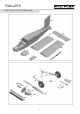
User Manual
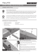

Step 5: Receiver Installation
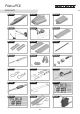
To make it easy to sh the servo leads through the battery hatch, make a wire hook about 25 cm long using mild steel wire.
The servo leads are numbered 1 through 7 with each number referencing the following control surface:
1. Left aileron
2. Elevator
3. Rudder
4. Throttle
5. Right aileron
6. Left landing ap
7. Right landing ap
The servo connectors can now be plugged into the receiver. Fix the receiver under the wing using a small piece of hook-and-
loop tape (Part #s 26 & 27)
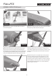
Step 7: Recommended Control Surfaces
As a baseline we recommend the following control surface travels and setups. Once you become familiar with the model you
can tailor the setting to your own preferences.
Rudder: 1 ¼ in (30 mm) (~35°) right / left, approx. 40% Expo
Elevator: 1 in. (25 mm) up, < ½ in. (12 mm), approx. 50% Expo
Ailerons: ½ in (13 mm) up, < ½ in. (12 mm) down, approx. 50% Expo
Landing Flaps: 90° down, with approx. 3mm down-elev. trim compensation, approx. 0.8 sec. delay
Step 8: Finishing
The model is supplied with two ame stickers 28 for decorating the aircraft. Apply these in the position shown on the
packaging illustrations.
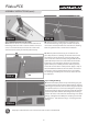
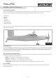
Step 6: Balancing
Position the ight battery on the battery tray in such a way that the model balances at the 2 ¼ in. (58 mm) point as measured
from the wing leading edge on both sides of the fuselage. When you are satised, x the battery in place using the hook-and-
loop straps supplied. We recommend applying a few drops of Cyanoacrylate glue to the hook-and-loop straps to x them
permanently to the bottom of the fuselage.
ASSEMBLY INSTRUCTIONS (cont.)
STEP 4B
58mm
9
PilatusPC6