
User guide

11
INSTALLATION
Mounting The Multi 4 Box
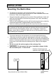
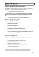
• The Multi 4 box should be mounted horizontally or vertically with
connectors to the bottom with a minimum of 75mm clearance at the base
of the box. Refer to the diagram below.
• Using the template supplied (see the centre of this handbook), locate and
mark the centre position of the two fixing screws. Drill, and if necessary,
plug the fixing holes.
• Screw in the roundhead screw that will fit into the keyhole slot, so that the
screw head protrudes by approximately 2mm from the wall.
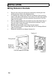
• Undo the retaining screw and remove the cover from the end of the box .
To prevent damage to the equipment you should heed the following:
• Place the box over the screw you have placed in the wall, such that the
screw drops into the keyhole slot. Slide the box to lock the screwhead into
position. If necessary adjust the screw to ensure that the box is held firmly
to the wall. Insert and screw the retaining screw. Refer to the diagram
below.
• Do not connect the mains supply or the exchange line.
•
WARNING: Do not remove top cover, hazardous voltages inside.
No serviceable parts. If removed all
Caution:
The equipment is fitted with semiconductor devices which may be damaged
by static electricity discharged by people, tools or test gear. To prevent
damage, ensure that no contact is made with any of the electronic circuitry,
when installing the equipment.
Position of retaining screw
(remove cover to gain access)
Key hole slot on rear of Multi 4 Box
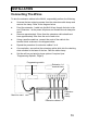
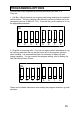
Programming
switch