Telephone System • • Installation Instructions User Guide Multimessage Systems Ltd 1
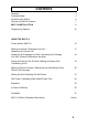
CONTENTS Contents Technical Notes 3 4 Introducing the Multi 4 Summary of Multi 4 Features 6 7 MULTI 4 INSTALLATION 8 Programming Options 15 USING THE MULTI 4 Tones used by MULTI 4 16 Making an Internal / Exchange Line Call / Answering An Internal Call 17 Answering An Exchange Line Call / Answering An Exchange Line Call - When All Extensions Are Busy 18 Putting an External Call On Hold / Making an Enquiry Call / Transferring a Call 19 Making a Remote Transfer / Setting Up And Cancelling Prior
TECHNICAL NOTES 1 The Multimessage Systems MULTI 4 Telephone System is suitable for connection to Exchange lines which provide Multi-Frequency (MF) signalling. Multimessage Systems MULTI 4 can be used with Timed Break Recall (TBR). 2 Only connect apparatus which has been approved for connection to your analogue Public Switched Telephone Network.
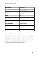
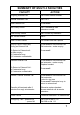
TECHNICAL NOTES - cont’d Exchange Line MF REN of 3 Extensions MF REN of 4 Dimensions 261mm long x 102mm wide x 63mm deep (max) Weight 1kg Power Supply 220 - 240V AC 47-63 Hz Plug Fuse Rating 3 Amp. Power Consumption 16 watts maximum Temperature 0 to 40°C working, -20 to +70°C storage Relative Humidity 0 to 95% (non-condensing) (See notes below) How many telephones can you connect? This is important if you want to connect more than one piece of apparatus to each extension.
INTRODUCING THE MULTI 4 Multi 4 is a small telephone system intended for use in the home, office or small business. It serves up to four internal telephone extensions from one Exchange Line. It provides both a high quality intercom between extensions, and access to the outside line from each extension, with total privacy on all calls. It consists of a compact unit which can be wall-mounted in any convenient position, its small size and smart appearance helping to blend into its surroundings.
SUMMARY OF MULTI 4 FACILITIES FACILITY ACTION Outgoing External Call Dial 9 then external number Internal Extension Call Dial 1 to 4 Hold External Call Press recall Set Priority Phone Dial 7 followed by own extension number Clear Priority Phone Dial 70 from any extension Set ‘Do Not Disturb’ Dial 0 Clear ‘Do Not Disturb’ Lift handset and then replace Enquiry Call to Third Party During an External Call Press recall to hold external Call Dial extension - make enquiry To Return to External ca
INSTALLATION Tools Required To install the MULTI 4 system the following tools are required: • • • • Drill and No. 8 masonry bit Wire cutters and strippers Pozi screwdriver with flat head IDC insertion tool, if IDC telephone sockets used lnstallation Items Check List Please use the following check list to ensure that all items are available before you commence installation. • MULTI 4 Control Box with two No.
INSTALLATION • • • • Small screws to fix line jack sockets to wall/skirting board Cable ducting, if required Up to four approved telephones of the Multi-Frequency (MF) type Master Line Jack Socket (to public exchange). * This installation kit is required to complete the installation of the Multi 4. It can be purchased as a comprehensive kit with the Multi 4 or separately from an appropriate supplier.
INSTALLATION Extension Cabling Requirements Extension cabling must be made with single or multiple pair (PVC covered) 0.5mm diameter tinned copper wire with overall PVC sheath. Cable to BT Specification CW 1308 is recommended. Multipair cable (e.g. 4-pair) is useful when more than one extension is run in the same direction from the MULTI 4 Box.
INSTALLATION Mounting The Multi 4 Box • • • • The Multi 4 box should be mounted horizontally or vertically with connectors to the bottom with a minimum of 75mm clearance at the base of the box. Refer to the diagram below. Using the template supplied (see the centre of this handbook), locate and mark the centre position of the two fixing screws. Drill, and if necessary, plug the fixing holes.
INSTALLATION Wiring Extension Sockets • Remove the cover from the line jack sockets by releasing the two holding screws. Refer to the diagram below. If necessary drill and plug the wall at the positions of the mounting holes on the back of the socket. Pierce one of the cable entry points and screw the socket to the wall using two fixing screws. Feed the cable into the socket . Remove approximately 5cm of sheath from the cable.
INSTALLATION Connecting The Wires To wire the extension cables to the Multi 4, sequentially perform the following: • Unscrew the two retaining screws from the extension cable clamp and remove the clamp. Refer to the diagram below. • Feed the extension 1 cable into the Multi 4 box through the hole in the end. Extension 1 is the power fail phone and therefore must always be wired. • Remove approximately 15mm from the extension cable sheath and bare approximately 5mm from the end of each wire.
INSTALLATION Checking Out The System • • • • • • • • • Ensure that all the phones are operative, set to Tone and Timed break recall (usually marked as T, TB, DTMF& TBR,MF&TBR). Please note that the Multi 4 does not support the use of phones which are PULSE, LOOP DISCONNECT (LD) or EARTH RECALL(E,ER). Check there are no wiring mistakes and that all the extension phones are plugged in. Plug in the Multi 4 ac mains lead and switch on. Do not plug into the exchange line master socket yet.
PROGRAMMING OPTIONS There are two main programming features provided by the MULTI 4. They are: 1. Call Bar - Which prevents any outgoing calls being made from the selected call bar phone. The only outgoing calls which the call bar will allow are to the emergency services (9 999 or 9 112). To set call bar, put the switch to ‘on’ for the appropriate extension. ON 1 2 3 4 5 6 7 8 2.
USING THE MULTI 4 The MULTI 4 offers the user many powerful features not available when telephones are connected through ordinary parallel extensions. Furthermore, this has been achieved without sacrificing the incomparable economy and versatility offered by simple, standard telephones. Because of this, your telephone keypad is called on to perform many more functions than the customer dialling of another subscribers number.
USING THE MULTI 4 Making An Internal Call • Lift handset. • Listen for internal dial tone. • Dial the required extension number.The extensions are numbered to 4. • Listen for ring tone. If the called extension is busy you will hear the engaged tone. At the end of the call, or if there is no answer, replace the handset. Making An Exchange Line Call • Lift handset. • Listen for internal dial tone. • Dial 9. • Listen for external dial tone. • Dial required number.
USING THE MULTI 4 Answering An Exchange Line Call An incoming call from the exchange line causes all extensions to ring, unless call intercept (priority phone), do not disturb, or no incoming calls are set. A double ring repeated every three seconds indicates an outside call. If you can hear more than one extension, you will notice that the sounds do not coincide. The sequence Is: Extensions 1 and 3 ring together, then Extensions 2 and 4 ring together.
USING THE MULTI 4 Putting An External Call On Hold An outside call, whether incoming or outgoing, can be held while an enquiry call is made or the call is transferred to another extension. • To put the call on hold, press RECALL, once. If it is an outgoing call, i.e. you originated it yourself, you must wait 20 seconds after dialling the last digit before attempting to hold the call. • To cancel hold and return to the held caller, press RECALL.
USING THE MULTI 4 If the enquiry extension is engaged or does not answer, return to the exchange by pressing RECALL. Making A Remote Transfer When your extension is connected to an outside call, you can make a transfer to another extension (a remote extension), before the remote extension answers. • With the outside call established, press RECALL. • Dial the required extension number. • Listen for ring tone. • Replace your handset.
USING THE MULTI 4 • Lift handset. • Listen for internal dial tone. • Dial 7 followed by own extension number • Listen for confirmation tone. • Replace handset. • Your extension is now the Priority Phone To Cancel Call lntercept (Priority Phone) • Lift handset of any extension • Listen for internal dial tone • Dial 70. • Listen for confirmation tone.
USING THE MULTI 4 • Lift handset at appropriate extension. • Replace handset. Call Pick-Up It is possible to pick - up an external call ringing at a different extension by: • Lift handset • Listen for internal dial tone. • Dial 6. The call will now be connected to your extension. Operating When Mains Power Fails In the event of a mains power failure, the telephone at extension 1 is connected directly to the exchange line. The line is then accessed from this extension without dialling 9.
USING THE MULTI 4 Examples To telephone Line 1 EXT 2 3 4 This is a basic system arrangement, with 4 standard telephones. To telephone Line 1 EXT 2 3 4 3 telephones and a fax machine. Fax machines are recommended to be connected to extension 4, because if the fax option card is fitted it will only use extension 4.
USING THE MULTI 4 Examples To telephone Line 1 EXT 2 3 4 3 telephones and 1 PC with a modem. You can also have a fax machine parallel to the PC if desired. To telephone Line 1 EXT 2 3 4 3 telephones and 1 answer machine with another telephone.
USING THE MULTI 4 In Case Of Difficulty These notes should be of assistance, if you ever encounter any difficulty in using the MULTI 4. Remember that an outside call cannot be made from a call barred extension (other than a 9 999 or 9 112 call) - make sure that the Call Barring settings are set to your requirements. Be careful not to leave an outside call on hold by accident. If in doubt press recall to check. If public network dial tone is received, clear the system by replacing the handset.
When using speed Dial/modem it is important to make sure that you program a pause after dialling 9. Please refer to the manufacturers user guide. If after installing the system the extensions do not ring, please check that Master Line Jack Sockets have been used.
GUARANTEE Multimessage Systems Ltd. guarantees this product for one year from the date of purchase provided that: • • • The product has only been used for its intended purpose, and has not been subjected to misuse, or been wilfully or accidentally damaged. The product has been installed according to the maker's lnstallation Instructions. The product has not been tampered with or repaired by anyone other than Multimessage Systems Ltd. or its approved agents.
Dealers stamp APPROVED for connection to telecommunication systems specified in the instructions for use subject to the conditions set out in them. 504391 Multimessage Systems Ltd. Unit 2 / 3, Furzewood House, Cranborne Industrial Estate, Cranborne Road, Potters Bar, Herts. EN6 3JN Tel. ++44 (0) 1707 644480 Fax ++44 (0) 1707 646745 Part No.