
User guide


Passive+Relay Version 8.19 page 8
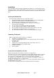
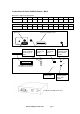
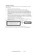
Connections on front and rear panels - M310L
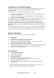
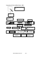
M310 Krone Strip Connection Details
Krone strip 1 2 3 4 5 6 7 8 9 10
Announcer line
2 3 4 5 6 7 8 9 10 11
Krone strip 1 2 3 4 5 6 7 8 9 10
Announcer line
12 13 14 15 16 17 18 19 20 21
Krone strip 1 2 3 4 5 6 7 8 9 10
Announcer line
22 23 24 25 26 27 28 29 30 31
Krone strip 1 2 3 4 5 6 7 8 9 10
Announcer line
32 NU NU NU NU NU NU NU NU NU
NU = Not Used
MULTIMESSAGE SYSTEMS
MULTILINE ANNOUNCER M310
MAINS ON
LOCAL
HANDSET
ACTIVE LINES
LOCAL
EXTERNAL
AUDIO
INPUT
EXTERNAL
AUDIO
OUTPUT
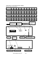
MULTIMESSAGE SYSTEMS LTD
TEL No. (+44) 01707 644480 FAX No. (+44) 01707 646745
MODEL No: 310 SERIAL No: 3281
DESIGNED AND MANUFACTURED IN THE U.K
TELEPHONE
LINE
SYSTEM CONFIGURATION
BATTERY FUSE
5 AMP
THIS FUSE MUST BE
REMOVED WHEN
NOT IN SERVICE
WARNING-THIS APPARATUS MUST
BE EARTHED
CAUTION: MAINS VOLTAGE
Disconnect mains supply
before removing covers
~240 V 50. . 60 Hz 30 W
MAINS FUSE
250 mA (T)
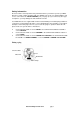
Socket for
connecting audio
input from tape
recorder
Port 1 local handset
indicator (on when
port is busy)
Port indicators
(on when port
is busy)
Socket for
connecting phone
Display
Software
configuration
label
Mains fuse
Socket for connecting audio
input to tape recorder
Mains power
indicator light
Mains input socket Battery fuse holder Telephone line cable