
User manual


ill.6
b
b
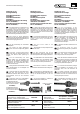
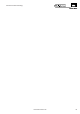
(ill.6)
Mass b nach folgender Ta-
belle kontrollieren:
(ill.6)
Check dimension b
according to the follow-
ing table:
(ill.6)
Contrôler la largeur b sui-
vant le tableau ci-
dessous:
Typ b Kontrollmass Leitungsquerschnitt
Type b control dimension Conductor cross section
Type b largeur de contrôle Section du câble
mm mm AWG
PV-ADSP4/2,5 3 1,5 - 2,5 14
5 4-6 12/10
3
5 4 - 6 12/10
2
PV-ADSP4/6
PV-ASBP4/2,5 1,5 - 2,5 14
PV-ADBP4/6
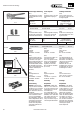
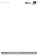
(ill.7)
Leitung abisolieren.
L = 6 - 7,5mm.
Darauf achten, dass keine
Einzeldrähte abgeschnitten
werden.
Empfohlenes Werkzeug:
Abisolierzange PV-AZM,
Bestell-Nr. 32.6027.
(ill.7)
Strip cable insulation.
L = 6 - 7,5mm.
Take care not to cut indivi-
dual strands.
Recommended tool:
Stripping pliers PV-AZM,
Order No. 32.6027.
(ill.7)
Dénuder le câble.
L = 6 - 7,5mm.
Veillez à ne pas couper
les brins.
Outil recommandé:
Pince à dénuder PV-AZM,
No. de Cde 32.6027.
PV-AZM
L
ill.7
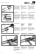
Crimpen Crimping Sertissage
(ill.8)
Hinweise zur Bedienung
der Crimpzangen siehe
MA251 (de_en_fr)
(www.multi-contact.com)
(ill.8)
Notes to the operation of
the crimping pliers,
seeMA251 (de_en_fr)
(www.multi-contact.com)
(ill.8)
Notice d’utilisation des
pinces à sertir, voir
MA251 (de_en_fr)
(www.multi-contact.com)
Montageanleitung
Assembly Instructions
Instructions de montage
MA251 (de_en_fr)
ill.8
ill.9
max. 7
x
12,5
12,5
+0,2
- 0,4
+0,2
- 0,4
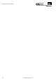
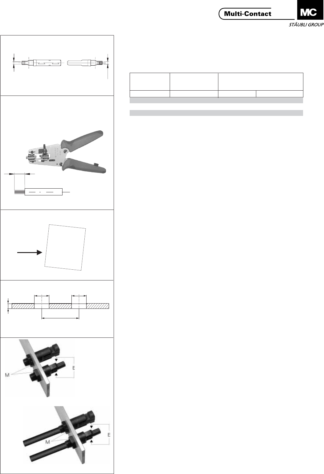
(ill.9)
Gehäusewand bohren ge-
mäss Illustration.
Bei horizontal oder Verti-
kal Einbau, empfehlen wir
einen Rasterabstand (X)
von 35 mm.
Auch ohne Sicherheitshül-
se PV-SSH4 empfehlen
wir einen Rasterabstand
(X) von mindestens 25
mm.
(ill.9)
Drill the box wall accor-
ding to the illustration.
For both horizontal and
vertical mounting we re-
commend a distance (x)
of 35 mm. Even without
the safety lock clip PV-
SSH4 we recommend a
minimum distance (x) of
25 mm.
(ill.9)
Percer la paroi du boîtier
selon l’illustration.
Pour les montages hori-
zontaux ou verticaux,
nous préconisons un en-
traxe (X) de 35mm. Sans
le clip de sécurité PV-
SSH4 cet entraxe (X) peut
être ramené à une valeur
minimale de 25mm.
Montage Installation Montage
(ill.10)
Kunststoffteile so ausrich-
ten (E), dass sie gesteckt
und getrennt werden kön-
nen. Die Mutter M fest-
schrauben und mit 2Nm
anziehen.
(ill.10)
Position the insulators (E)
so that they can be plug-
ged and unplugged.
Screw-on the nut and
tighten with the torque
spanner.
Tightening torque 2Nm.
(ill.10)
Introduire l'isolant dans le
boîtier, orienter verticale-
ment (E) les clips d'en-
clenchement et serrer
l'écrou M avec la clé dyna-
mométrique. Couple de
serrage: 2Nm.
ill.10
ohne Leitung
without cable
sans câble
mit Leitung
with cable
avec câble
3/8
www.multi-contact.com
Advanced Contact Technology