Wireless-System Manual
Information in this document is subject to change without notice. No part of this document may be reproduced or transmitted without the express written permission of Multi Channel Systems MCS GmbH. While every precaution has been taken in the preparation of this document, the publisher and the author assume no responsibility for errors or omissions, or for damages resulting from the use of information contained in this document or from the use of programs and source code that may accompany it.
Table of Contents Introduction About this Manual Welcome to the Wireless Recording System 1 1 2 Important Information and Instructions Important Safety Advice Guarantee and Liability Operator's Obligations 3 3 4 4 Hardware Headstage Receiver USB Interface 5 5 7 8 Software Installing MC_Rack Starting MC_Rack 9 9 11 Operating a Wireless System Experimental Setup Operating Modes 19 19 21 Troubleshooting Troubleshooting Error Messages 23 23 23 Appendix Wireless-System Config Technical Support Techni
1 Introduction 1.1 About this Manual This manual comprises all important information about the first installation of the hardware and software, and about the daily work with the instrument. It is assumed that you have already a basic understanding of technical and software terms. No special skills are required to read this manual.
Wireless System Manual 1.2 Welcome to the Wireless Recording System The innovative wireless recording in vivo system is the all-in one solution for amplifying, recording, and analyzing in vivo data from four, eight, sixteen or thirty-two channels. The bandwidth of the amplifier is 1 Hz to 5 kHz. The sampling rate is software controlled and user defined. With a resolution of 16 bit the accuracy of your data is guaranteed.
2 Important Information and Instructions 2.1 Important Safety Advice Warning: Make sure to read the following advice prior to install or to use the device and the software. If you do not fulfill all requirements stated below, this may lead to malfunctions or breakage of connected hardware, or even fatal injuries. Warning: Obey always the rules of local regulations and laws. Only qualified personnel should be allowed to perform laboratory work.
Wireless System Manual 2.2 Guarantee and Liability The General conditions of sale and delivery of Multi Channel Systems MCS GmbH always apply. The operator will receive these no later than on conclusion of the contract. Multi Channel Systems MCS GmbH makes no guarantee as to the accuracy of any and all tests and data generated by the use of the device or the software. It is up to the user to use good laboratory practice to establish the validity of his findings.
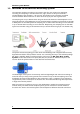
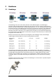
3 Hardware 3.1 Headstage The headstage is the first of the three elements of the Wireless-System. The headstage is extremely small and lightweight and allows the recording of neuronal activity in freely moving animals. The A/D conversion with a variable sampling rate of 1, 2, 4, 5, 10 and 20 kHz when using all channels and 25, 32 and 40 kHz when using four or less than four channels of the W8-System or one or two channels of the W4-System.
Wireless System Manual The connector of the headstage is connected to the electrode which is implanted into the brain of the laboratory animal. The external connector of the implanted electrode is fixed, for example with dental cement. For maximum flexibility, MCS offers headstages with connections to all probes on request. The headstage records analog signals from the electrodes.
Hardware 3.2 Receiver The receiver is the second element of the Wireless-System. The receiver of the Wireless-System receives the digitized signals sent from the headstage in a distance of about 5 m. The device is equipped with four antenna to prevent data loss. Two Lemo connectors on the front panel, labeled with D0 and D1 are available to feed in TTL signals for synchronization of the Wireless-System with other devices.
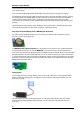
Wireless System Manual 3.3 USB Interface The USB interface board is the third element of the Wireless-System. The interface board is connected to the receiver with a MCS Bus cable, which is about 5 m long. Longer cables are delivered on request. The advantage is that the interface board can be placed near to the data acquisition computer in a different room than the experimental laboratory and the test animal will not be disturbed in excess of the experimental setup and the scientist.
4 Software 4.1 Installing MC_Rack The data acquisition computer with the MC_Rack program comes preinstalled and preconfigured by MCS for a flawless operation. You should contact your local retailer for assistance if you want to install additional hard- or software, or if you want to replace the computer, as incompatibilities of hardware components or software settings with MC_Rack may occur. Caution: You have acquired a high performance data acquisition and analysis computer.
Wireless System Manual Recommended operating system settings The following automatic services of the Windows operating system interfere with the data storage on the hard disk and can lead to severe performance limits in MC_Rack. These routines were designed for use on office computers, but are not very useful for a data acquisition computer. Turn off Windows System Restore. Turn off automatic Windows Update. Deselect Windows Indexing Service for all local disks.
Software 4.2 Starting MC_Rack Connect, for example, a W8-System via USB high speed cable to the data acquisition computer. Open MC_Rack program. In "Edit" menu choose "Data Source Setup". The following “Channel Layout” dialog appears. Select USB-MEA in the left drop down menu of "Data Source". The W8-System "MCS WPA8 (S/N xxxx)" will automatically appear in the right drop down menu. In "Source Layout" the check box “1 dimensional” is predefined and the "Number of Channel" in total is “8”.
Wireless System Manual There is an additional window in “Hardware” tab for the W8-System called “Wireless”, and the MC_Rack display shows an additional status line The “Sampling Frequency” of the system depends on the number of channels which are in use. When recording with all eight available channels the sampling rate is limited to 20 kHz. Recording with one to four channels only is possible with a sampling frequency of up to 40 kHz.
Software Wireless Window The additional window “Wireless” is for software control of the wireless system. In “Select Headstage” you can select one of the four headstages A, B, C, and D if more than one headstage is connected to the system. After pressing the button “Scan” the receiver scans which headstages are available. Then the user is able to select the desired headstage. The appropriate channels of the selected headstage are chosen by clicking on the channel number.
Wireless System Manual Strategies for Saving Energy The standard recording time with a fully charged battery is 120 minutes at 20 kHz and 0 dB output power in a range of up to 5 m between headstage and receiver. Please read chapter "Power Consumption" in the Appendix. To prolong the recording time until the battery has to be recharged on the one hand you can decrease the sampling frequency, on the other hand you can decrease the RF output power.
Software Software Settings when Using different Types of Headstages with one Wireless-System May be you will use your wireless system in different experimental setups, that is for example, first with an eight channel headstage and then with a four channel headstage. In this case you have to adapt the wireless system to the variable hardware requirements via MC_Rack software. MC_Rack needs specified driver units for each hardware component, which must be loaded when changing the type of the headstage.
Wireless System Manual The installation lasts a few seconds. Please wait until the new driver has been loaded and the headstage is internally switched. If you install the W4 headstage for the first time, a hardware installation assistant will appear. Please follow the installation instructions. If the drivers for the W4-System have been installed before, ignore this step and click the “Refresh” button in the “Data Source Setup” dialog.
Software After the hardware installation process, please click the “Refresh” button in the “Data Source Setup” dialog to update hardware and software. The W4-System will now be available in the “Data Source Setup” dialog. Select the desired headstage device from the drop down menu and start working as described above.
5 Operating a Wireless System 5.1 Experimental Setup First step to set up an experiment with the wireless system is to implant an electrode into the laboratory animal. The electrode has to be fixed, for example with cement used in dental technic, to guarantee a tight position of the electrode in the desired area of the brain. The electrode connector must be available on the skin surface of the animal. Implant a ground option additionally, if necessary.
Wireless System Manual To make sure that the animal and the headstage are set to the same electrical potential, a grounding connection is also necessary. A good ground option is usually a large conductor, such as a screw or a silver wire implanted under the skin of the animal. Experimental Setup Connect the receiver to the USB interface, and the USB interface to the data acquisition computer. Switch on the computer and start the MC_Rack program.
Operating a Wireless System 5.2 Operating Modes Recording Mode Set up all components of the Wireless-System. Start MC_Rack and add the Wireless-System as data source. Please read chapter “Starting MC_Rack”. Define the amplifiers gain of 100 and select the sampling frequency in the “Hardware” tab. Make sure the storage battery is completely charged. Connect the battery to the white connector on the headstage.
Wireless System Manual Operating up to four Headstages rotatory with one Wireless-System It is possible to operate up to four different headstages connected to one Wireless-System in a rotatory system. The headstages are discriminated via frequency band for the radio communication. Each headstage is labeled with a letter (A, B, C, D). Please see the bill of delivery for the assignment of the headstage and the frequency band.
6 Troubleshooting 6.1 Troubleshooting Most problems occur seldom and only under specific circumstances. In most cases, it is only a minor problem that can be easily avoided or solved. If the problem persists, please contact your local retailer. The highly qualified staff will be glad to help you. Please inform your local retailer as well, if other problems that are not mentioned in this documentation occur, even if you have solved the problem on your own.
7 Appendix 7.1 Wireless-System Config The tool "Wireless-System Configuration" helps to configure new wireless headstages to a present setup and to arrange the assignments of headstages of several systems for simultaneous use. Additional it is possible to change the high pass settings of the respective Wireless-System.
Wireless System Manual At first the software detects all Wireless-Systems which are connected to one data acquisition computer. In "Found W-System SN" the systems are defined by the serial number. You can find the serial number on the bottom of the receiver and interface board. It is possible to connect, for example, one W4- and one W8-System. Please set the number of channels of your system from the "W-Type" drop down menu.
Appendix Click the button "Distribute default" ID 1 to ID 4. to keep the "Frequency ID" in a line, If you try to give the same frequency ID to different systems you get an error message. "Frequency ID each ID must be different!". Please choose another ID. When using a second data acquisition computer nearby to record from an additional wireless systems, please make sure that the frequency IDs differ from each other. Otherwise the systems will interfere.
Wireless System Manual To Do Checklist before start working with a Wireless-System in a new configuration: 1. Start the Wireless-System Config program. The main window opens. 2. When connecting more than one Wireless-System to the data acquisition computer the main window appears twice or more. Please make sure that each system on one data acquisition computer has a different frequency ID. Your Wireless-System(s) is / are now detected by the Wireless-System Config tool.
Appendix 7.2 Technical Support Please read the "Troubleshooting" part of the manual or help first. Most problems are caused by minor handling errors. Contact your local retailer immediately if the cause of the trouble remains unclear. Please understand that information on your hardware and software configuration is necessary to analyze and finally solve the problem you encounter.
Wireless System Manual 7.3 Technical Specifications The Wireless-System is a 4-, 8-, 16- or 32-channel wireless in vivo system with headstage, receiver and interface board. Analog signals are converted in digital data streams in real-time. Warning: The devices may only be used together with Wireless-Systems from Multi Channel Systems MCS GmbH, and only for the specified purpose. Damage of the devices and even fatal injuries can result from improper use.
Appendix Storage battery Storage battery Lithium polymer, rechargeable Storage battery life until recharge (100 mAmh) 4 channels: 3.5 hours (recording @ 20 kHz) 8 channels: 2 hours (recording @ 20 kHz) 16 channels: 2 hours (recording @ 10 kHz) 32 channels: 1.3 hours (recording @ 5 kHz) for all channels: 80 days (in stand-by mode) Dimensions (W x D x H) of battery 17 mm x 11 mm x 3 mm (30 mAh battery) 26 mm x 19.5 mm x 2.3 mm (100 mAh battery) 26 mm x 20 mm x 4.5 mm (200 mAh battery) 27.5 mm x 19.
Wireless System Manual 7.
* multichannel systems Wireless Headstages Technical Specifications of Wireless Headstages W4-Headstage W8-Headstage Single row connector Omnetics or single row con. W16-Headstage Omnetics connector W32-Headstage Omnetics connector Technical Specifications Headstage Number of channels 4, 8, 16 or 32 Dimensions (W x D x H) (w/o antennae in mm) W4 W8 W16 W32 13 x 13 x 5 16 x 16 x 5 16 x 16 x 6.5 16 x 16 x 7.5 Weight (w/o battery) W4 W8 W16 W32 2.2 g 2.9 g 3.6 g 3.
* multichannel systems Wireless Headstages Technical Specifications of Wireless Headstages 30 mAh Battery 100 mAh Battery 200 mAh Battery 300 mAh Battery Technical Specifications Batteries Dimensions in mm 30 mAh battery 100 mAh battery 200 mAh battery 300 mAh battery Weight in g Length Width Height Weight 17 26 26 27.5 11 19.5 20 19.5 3 2.3 4.5 5 1.5 3.1 4.6 6.
* multichannel systems W4-Headstage Pin Layout of the 4-Channel Headstage for the Wireless Recording System W4-Headstage top side: The white connector is for the storage battery. Please use this connector for orientation of the headstage. W4-Headstage bottom side: Connector for the electrode probe or for the ME/W-Signal generator W4-Headstage with single row socket Diagram of the bottom side with pin layout: Please orientate the headstage as shown in the diagram.
* multichannel systems W4-Headstage Technical Specifications W4-Headstage Number of channels 4 Dimensions (W x D x H) (w/o antennae) 13 x 13 x 5 mm Weight (w/o battery) 2.2 g Amplifier integrated in the Headstage Bandwidth 1 Hz to 5 kHz (0.1 Hz on request) Resolution 16 bit Sampling rate 4 channels simultaneously 2 channels simultaneously 20 kHz 40 kHz Input voltage range + / - 12.
* multichannel systems W8-Headstage Pin Layout of the 8-Channel Headstage for the Wireless Recording System W8-Headstage top side: The white connector is for the storage battery. Please use this connector for the orientation of the headstage. W8-Headstage bottom side: Connector for the electrode probe or the ME/W-Signal generator. W8-Headstage with single row socket Diagram of the bottom side with pin layout. Please orientate the headstage as shown on the diagram.
* multichannel systems W8-Headstage Pin Layout of the 8-Channel Headstage for the Wireless Recording System W8-Headstage bottom side: Connector for the electrode probe or the ME/W-Signal generator via the adapter ADPT-Om-ME/W-SG. W8-Headstage top side: The white connector is for the storage battery. Please use this connector for the orientation of the headstage. W8-Headstage with Omnetics socket Diagram of the bottom side with pin layout. Please orientate the headstage as shown on the diagram.
* multichannel systems W8-Headstage Technical Specifications W8-Headstage (Omnetics or single row connector) Number of channels 8 Dimensions (W x D x H) (w/o antennae) 16 x 16 x 5 mm Weight (w/o battery) 2.9 g Amplifier integrated in the Headstage Bandwidth 1 Hz to 5 kHz (0.1 Hz on request) Resolution 16 bit Sampling rate 8 channels simultaneously 4 channels simultaneously 2 channels simultaneously 20 kHz 40 kHz 40 kHz Input voltage range + / - 12.
* multichannel systems W16-Headstage Pin Layout of the 16-Channel Headstage for the Wireless Recording System W16-Headstage bottom side: Connector for the electrode probe or the ME/W-Signal generator. W16-Headstage top side: The white connector is for the storage battery. Please use this connector for the orientation of the headstage. W16-Headstage with Omnetics connector A79039-001 (NSD-18-DD-GS) Diagram of the bottom side with pin layout. Please orientate the headstage as shown on the diagram.
* multichannel systems W16-Headstage Technical Specifications W16-Headstage Number of channels 16 Dimensions (W x D x H) (w/o antennae) 16 x 16 x 6.5 mm Weight (w/o battery) 3.6 g Amplifier integrated in the Headstage Bandwidth 1 Hz to 5 kHz (0.1 Hz on request) Resolution 16 bit Sampling rate 16 channels simultaneously 8 channels simultaneously 4 channels simultaneously 2 channels simultaneously 10 kHz 20 kHz 20 kHz 20 kHz Input voltage range + / - 12.
* multichannel systems W32-Headstage Pin Layout of the 32-Channel Headstage for the Wireless Recording System W32-Headstage top side: Please use the white connector for the storage battery for the orientation of the headstage. W32-Headstage bottom side: Connector for the electrode probe or the ME/W-Signal generator. W32-Headstage with Omnetics connector A79023-001 (NSD-36-DD-GS female, 4 guide posts) Diagram of the bottom side with pin layout. Please orientate the headstage as shown on the diagram.
* multichannel systems W32-Headstage Technical Specifications W32-Headstage Number of channels 32 Dimensions (W x D x H) (w/o antennae) 16 x 16 x 7.5 mm Weight (w/o battery) 3.7 g Amplifier integrated in the Headstage Bandwidth 1 Hz to 5 kHz (0.1 Hz on request) Resolution 16 bit Sampling rate 32 channels simultaneously 16 channels simultaneously 8 channels simultaneously 4 channels simultaneously 2 channels simultaneously 5 kHz 10 kHz 10 kHz 10 kHz 10 kHz Input voltage range + / - 12.
Appendix 7.5 Power Consumption To determine the battery life-time divide the capacity of the battery in use by the current drawn by the headstage. Please see the following table for the power consumption. Example: Using a 100 mAh battery with a W4-System, sampling at 0.5 kHz with all four channels, you have a battery life of approximately 100 mAh / 13.
Tabelle1 Power consumption of the Wireless Headstage in different operation modes [mA] 11/12/19 W32 Number of Channels: 1 RF Output Power [dB]: 0 -6 -12 -18 0 2 -6 -12 -18 0 3 -6 -12 -18 0 4 -6 -12 -18 0 5 -6 -12 -18 0 6 -6 -12 -18 0 7 -6 -12 -18 0 8 -6 -12 -18 38,2 38,3 38,3 38,4 38,7 39 39,7 39,4 41,1 x x x x 38,2 38,2 38,3 38,3 38,6 38,9 39,5 39,8 40,7 x x x x 38,2 38,2 38,3 38,3 38,5 38,8 39,3 39,7 40,4 x x x x 38,2 38,2 38,3 38,3 38,5 38,8 39,3 39,6 40,3 x x x x
Tabelle1 W16 Number of Channels: 1 RF Output Power [dB]: 0 -6 -12 -18 0 2 -6 -12 -18 0 3 -6 -12 -18 0 4 -6 -12 -18 0 5 -6 -12 -18 0 6 -6 -12 -18 0 7 -6 -12 -18 0 8 -6 -12 -18 23,6 23,7 23,7 23,7 23,9 24 24,9 25,1 26,5 28,8 x x x 23,6 23,6 23,7 23,7 23,9 24 24,6 25 26 28,3 x x x 23,6 23,6 23,7 23,7 23,9 23,9 24,7 24,8 25,9 28 x x x 23,6 23,6 23,7 23,7 23,9 23,9 24,6 24,8 25,9 27,8 x x x 23,7 23,7 23,7 23,8 23,9 24,9 25,7 26,4 28,9 34,3 x x x 23,6 23,7 23,7 23,7 23,9 2
Tabelle1 W4 Number of Channels: 1 RF Output Power [dB]: 0 -6 -12 -18 0 2 -6 -12 -18 0 3 -6 -12 -18 0 4 -6 -12 -18 13,4 13,4 13,4 13,4 13,8 13,9 14,4 14,8 15,8 18,6 20 21,9 24 13,4 13,4 13,4 13,4 13,6 13,8 14,3 14,6 15,5 18 19,2 21 22,8 13,3 13,3 13,4 13,4 16,6 13,8 14,3 14,5 15,4 17,7 18,8 20,4 22,1 13,3 13,3 13,4 13,4 13,5 13,7 14,2 14,5 15,3 17,5 18,6 20,2 21,9 13,4 13,4 13,5 13,7 13,9 14,4 15,3 15,8 18,6 24 26,2 29,1 31,3 13,4 13,4 13,5 13,6 13,8 14,3 15 15,5 18 22,9 24,7 27,3 29
Wireless System Manual 7.
ME/W-SG Signal Generator for the ME-Systems and the Wireless-System The ME/W-Signal Generator is a very convenient tool for users of the Wireless-System and / or for users of ME-Systems. Use the ME/W-SG instead of setting up a complete experiment for training, controlling, and troubleshooting purposes. 10-pin single row connector for W4 and W8 (single row) and MPA8I headstages. Battery 40-pin Omnetic connector for W32 headstage and for μPA32 preamplifier.
ME/W-SG Signal Generator for the ME-Systems and the Wireless-System Switch ME/W-SG on: Press the control button. Switch off: Press control button longer than two seconds. Switch Position 1 Switch Position 2 Control Button press n times OFF OFF ME/W-SG ON ON OFF Signal Source Artificial Sine Wave (1.75 mV) 0.005 Hz Note: sine waves < 1 Hz might not be visible because of the hardware filter bandwidth. 1 Sine Wave 0.01 Hz 2 Sine Wave 0.03 Hz 3 Sine Wave 1.25 Hz 4 Sine Wave 12.
Appendix 7.7 Contact Information Local retailer Please see the list of official MCS distributors on the MCS web site. User forum The Multi Channel Systems User Forum provides the opportunity for you to exchange your experience or thoughts with other users worldwide. Mailing list If you have subscribed to the Mailing List, you will be automatically informed about new ssoftware releases, upcoming events, and other news on the product line. You can subscribe to the list on the MCS web site. www.
37
8 Index 39
Wireless System Manual 40
MCS Bus Cable .................................... 8 TTL Signals........................................... 8 B Backpack Battery 5 35 5 E Experimental Setup 23 H Headstage 5 A/D Converter......................................5 Electrode Connector ...........................5 Flasher ..................................................5 Funk Chip.............................................5 Storage Battery ...................................5 I Installing MC_Rack 11 Hardware ...........................
42