
Manual
Multi Channel Systems
MCS GmbH
Aspenhaustrasse 21
72770 Reutlingen
Germany
Fon +49-7121-9 09 25-
0
Fax
+49-7121-9 09 25-11
info@multichannelsystems.com
www.multichannelsystems.com
© 2014 Multi Channel Systems MCS GmbH
Product information is subject to change
without notice.
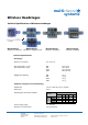
W16-Headstage
Pin Layout of the 16-Channel Headstage for the Wireless Recording System
multichannel
systems
*
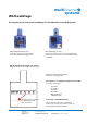
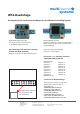
Please orientate the headstage
as shown on the diagram.
Pin Layout of the Omnetics connector
A79039-001 (NSD-18-DD-GS)
GND (Ground)
Channel 1 Channel 2
Channel 3 Channel 4
Channel 5 Channel 6
Channel 7 Channel 8
Channel 9 Channel 10
Channel 11 Channel 12
Channel 13 Channel 14
Channel 15 Channel 16
REF (Reference)
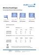
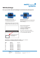
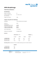
W16-Headstage top side:
The white connector is for the storage battery.
Please use this connector for the orientation
of the headstage.
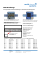
W16-Headstage bottom side:
Connector for the electrode probe
or the ME/W-Signal generator.
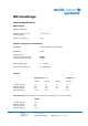
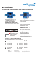
Connector for W16-Headstage
The Omnetics connector mates with
standard pin connector such as:
Through-Hole:
A79038-001 (NPD-18-DD-GS)
Horizontal Surface Mount:
A79040-001 (NPD-18-AA-GS)
Vertical Surface Mount:
A79042-001 (NPD-18-VV-GS)
Cable (18.0" 34 AWG lead-wire):
A79044-001 (NPD-18-WD-18.0-C-GS)
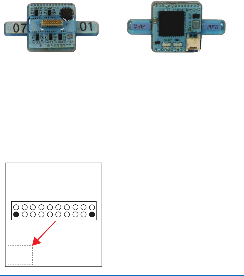
W16-Headstage with Omnetics connector
A79039-001 (NSD-18-DD-GS)
Diagram of the bottom side with pin layout.
2 4 6 8 10 12 14 16
GND 1 3 5 7 9 11 13 15 REF
Storage battery connector
on the opposite side
for orientation.