
Manual
Multi Channel Systems
MCS GmbH
Aspenhaustrasse 21
72770 Reutlingen
Germany
Fon +49-7121-9 09 25-
0
Fax
+49-7121-9 09 25-11
info@multichannelsystems.com
www.multichannelsystems.com
© 2014 Multi Channel Systems MCS GmbH
Product information is subject to change
without notice.
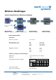
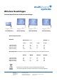
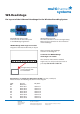
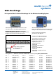
W8-Headstage
Pin Layout of the 8-Channel Headstage for the Wireless Recording System
multichannel
systems
*
W8-Headstage top side:
The white connector is for the storage battery.
Please use this connector for the orientation
of the headstage.
W8-Headstage bottom side:
Connector for the electrode probe
or the ME/W-Signal generator via
the adapter ADPT-Om-ME/W-SG.
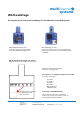
Connector for W8-Headstage
with Omnetics socket
The Omnetics connector mates
with standard pin connector such as:
Through-Hole:
A79038-001 (NPD-18-DD-GS)
Horizontal Surface Mount:
A79040-001 (NPD-18-AA-GS)
Vertical Surface Mount:
A79042-001 (NPD-18-VV-GS)
Cable (18.0" 34 AWG lead-wire):
A79044-001 (NPD-18-WD-18.0-C-GS)
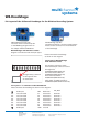
W8-Headstage with Omnetics socket
Diagram of the bottom side with pin layout.
Pin Layout of the Omnetics socket A79039-001.
Please orientate the headstage as shown on the diagram.
Guide post REF Reference
NC not connected E1 Electrode 1 Channel 1
NC not connected E2 Electrode 2 Channel 2
NC not connected E3 Electrode 3 Channel 3
NC not connected E4 Electrode 4 Channel 4
NC not connected E5 Electrode 5 Channel 5
NC not connected E6 Electrode 6 Channel 6
NC not connected E7 Electrode 7 Channel 7
NC not connected E8 Electrode 8 Channel 8
Guide post GND Ground
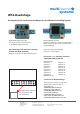
MC_Rack
Storage battery connector
on the opposite side
for orientation.
REF
GND
REF E1 E2 E3 E4 E5 E6 E7 E8 GND
NC NC NC NC NC NC NC NC
Please orientate the headstage
as shown on the diagram.