USB-MEA32-STIM4 Manual
Information in this document is subject to change without notice. No part of this document may be reproduced or transmitted without the express written permission of Multi Channel Systems MCS GmbH. While every precaution has been taken in the preparation of this document, the publisher and the author assume no responsibility for errors or omissions, or for damages resulting from the use of information contained in this document or from the use of programs and source code that may accompany it.
Table of Contents 1 1.1 1.2 Introduction About this Manual Welcome to the USB-MEA32-STIM4 1 1 2 2 2.1 2.2 2.3 Important Safety Advice Operator's Obligations Guarantee and Liability Important Safety Advice 3 3 3 4 3 3.1 3.2 3.3 Software Installation System requirements Recommended BIOS settings Driver Installation 5 6 6 7 4 4.1 USB-MEA32-STIM4-System The USB-MEA32-STIM4-System Components 4.1.1 Filter Amplifier 4.1.2 Data Acquisition 4.1.3 Stimulus Generator 4.1.4 Perfusion 4.1.
USB-MEA32-STIM4 Manual 5 5.1 5.2 vi 5.3 Recording and Stimulation 23 MC_Rack: Data Acquisition and Analysis 23 MC_Stimulus: Stimulation Control 28 5.2.1 Device Setup 28 5.2.2 Selection of Stimulation Electrodes 29 5.2.3 Programming of Stimulation Pulses and Triggers30 5.2.4 Triggering on Sync Out in MC_Rack 31 LTP-Director: Recording and Stimulation Software 32 6 6.1 6.2 6.3 6.
1 Introduction 1.1 About this Manual It is assumed that you already have a basic understanding of technical and software terms. No special skills are required to read this manual. If you are using the device for the first time, please read the Important Safety Advice before installing the hardware and software, where you will find important information about the installation and first steps. The device and the software are part of an ongoing developmental process.
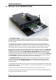
USB-MEA32-STIM4 Manual 1.2 Welcome to the USB-MEA32-STIM4 The USB-MEA32-STIM4 is a compact and portable stand-alone solution for extracellular recordings with integrated amplifiers, data acquisition, and a four channel current stimulus generator. Perfusion heating and the possibility to apply suction through perforated MEAs are also included. It is a highly compact system: The system acquires data from up to 32 electrode channels.
2 Important Safety Advice 2.
USB-MEA32-STIM4 Manual 2.3 Important Safety Advice Warning: Make sure to read the following advice prior to installation or use of the device and the software. If you do not fulfill all requirements stated below, this may lead to malfunctions or breakage of connected hardware, or even fatal injuries. Warning: Always obey the rules of local regulations and laws. Only qualified personnel should be allowed to perform laboratory work.
3 Software Installation There are two software options available to run an USB-MEA32-STIM4-System: Controlling the data recording and processing with MC_Rack in combination with MC_Stimulus for the stimulation, or working with LTP-Director. The LTP-Director controls the data acquisition and the stimulation as well. Please read the respective manuals or helps for detailed information. MC_Rack The recording and analysis software MC_Rack can be used to work with the USB-MEA32-STIM4System.
USB-MEA32-STIM4 Manual 3.1 System requirements Operating System: One of the following Windows ® operating systems is required: Windows 7, VISTA or XP (English and German versions supported) with the NT file system (NTFS). Other language versions may lead to software errors. Hardware (Not required for offline analysis or demo mode): The data acquisition board USB-MEA32-STIM4. If no USB-MEA32-STIM4 is present, MC_Rack / LTP-Director opens in a simulation mode.
Software Installation 3.3 Driver Installation The USB-MEA32-STIM4 is a plug and play device. The driver is automatically installed together with the MC_Rack / LTP-Director program. It is easier to install the software first and then connect the USB-MEA32-STIM4 to the data acquisition computer.
4 USB-MEA32-STIM4-System 4.1 The USB-MEA32-STIM4-System Components 4.1.1 Filter Amplifier The filter amplifier combines a band pass filter and the signal amplification in one instrument. The bandwidth of 0.5 Hz to 3000 Hz is suitable for a broad range of applications, such as spikes and field potential recordings. The digital filter of the MC_Rack program can be used to adjust the pass band and filter the raw data. Please see the MC_Rack help or manual for more information.
USB-MEA32-STIM4 Manual 4.1.2 Data Acquisition Electrode raw data are acquired from the special designed perforated MEA and digitized by the analog / digital converter board that is integrated into the main unit. Recorded signals are converted in real time into digital data streams at sampling rates of up to 50 kHz per channel. You will not miss even fast biological signals. Data is transferred to the computer via High Speed USB 2.0 port. 4.1.
USB-MEA32-STIM4-System Temperature Controller TC01/02 The USB-MEA32-STIM4 features a PH01 with a PT100 temperature sensor. If you connect a temperature controller TC01/02 to the heating element via D-Sub 9 connector, the heating element guarantees constant temperature conditions for the biological sample, placed on the pMEA-32S12-Lx. The TC01/02 can be controlled manually or by software TCX-Control. Please see the TCX manual for more information. 4.1.
USB-MEA32-STIM4 Manual Important: Do not autoclave or sterilize pMEAs by heat! This type of MEA is not heat stable and will be irreversibly damaged! For cleaning, rinse them with distilled water first, then apply 1% Terg-A-Zyme solution (Sigma) for several hours. Rinse the pMEA again with distilled water and dry them directly before use. Sterilization with 70 % ethanol is possible.
USB-MEA32-STIM4-System Perfusion The pMEA carrier is equipped with a glass ring. The ring is 6 mm high, and has an outer diameter of 24 mm. The ring can be used as perfusion chamber. The USB-MEA32-STIM2-System provides a PH01 (perfusion cannula) on top of the device. For perfusion you need a peristaltic pump, and for regulating the temperature of the perfusion medium a temperature controller TC01/02, connected to the PH01.
USB-MEA32-STIM4 Manual 4.3 The USB-MEA32-STIM4 Device 4.3.1 Front Unit for pMEA with Suction Port The perspex insert in front of the main unit contains the frame for the pMEA on top and the suction port below. A tube is connected to the small sealed compartment. By this tube, suction can be applied to the MEA from below either manually via syringe, or via controlled vacuum pump CVP. Holding Clamps To open the unit unlock the holding clamps on the left and on the right.
USB-MEA32-STIM4-System Contact Pins of the Amplifier When the unit is closed, the contact pins of the amplifier connect to the contact pads of the pMEA. The contact pins are arranged in five rows with nine pins each. Perfusion Cannula PH01 The PH01 is used for controlling the perfusion of the perfusion chamber on the pMEA. The connected temperature controller TC01/02 keeps the temperature of the perfusion medium constant.
USB-MEA32-STIM4 Manual 4.3.2 Rear Panel USB The USB connector is used to transfer the amplified and digitized data from all data channels and the additional digital channel to any connected data acquisition computer via High Speed USB 2.0 (type A - mini B) cable. Power In Connect the power supply unit. This power supply powers the USB-MEA32-STIM4 main unit only. The device needs 9 V and 1.3 A / 11.7 W.
USB-MEA32-STIM4-System 4.3.3 Connecting the USB-MEA32-STIM4 USB-MEA32-STIM4 is a highly compact system with integrated amplification, data acquisition, and analog / digital conversion. Via USB High Speed 2.0 it is possible to transfer a digitally converted and amplified data stream of up to 32 electrode channels to any data acquisition computer. Note: Using a USB hub for connecting the USB-MEA32-STIM4 to the computer is not recommended. The system needs a broad bandwidth for the data transmission.
USB-MEA32-STIM4 Manual 4.4 Working with the USB-MEA32-STIM4 Amplifier 4.4.1 Setting up the Amplifier For opening the lid of the amplifier, unlock the holding clamps on the left and on the right side. The upper part of the unit swings open to enter the pMEA. Now you can insert a test model probe or a perforated MEA into the frame. Below the place for the pMEA is a small sealed compartment that is connected to a tube. By this tube, suction can be applied to the MEA from below.
USB-MEA32-STIM4-System Place the Test-MEA32S12-Lx test model probe inside. Replace the upper unit, and close the holding clamps carefully. First Functional Tests Each MEA amplifier has been thoroughly tested at the factory site before delivery. However, you may want to perform some tests yourself before you begin your experiment to exclude any damage that might have occurred during transportation.
USB-MEA32-STIM4 Manual 4.4.2 Perfusion A PH01 perfusion cannula is already integrated on top of the USB-MEA32-STIM4-System. Connected to a TC01/02 temperature controller, it is possible to keep the temperature of the perfusion medium constant at the desired value. There is no heating from below as with the regular MEA amplifiers. To connect the perfusion cannula PH01, please read PH01 manual for detailed information. Bath or test solutions can be applied at flow rates from 500 μl to 4.5 ml per minute.
USB-MEA32-STIM4-System 4.4.3 Pressure Control in the Suction Port Pressure Control via CVP The pressure control unit CVP (controlled vacuum pump) is a vacuum pump with a pressure sensor and a waste bottle. A sensor measures the pressure in the compartment attached to the waste bottle, and can regulate the suction to maintain a constant negative pressure.
USB-MEA32-STIM4 Manual 4.4.4 Setting up an Experiment Open the lid of the amplifier. Place the pMEA32S12-Lx chip inside the USB-MEA32-STIM4 amplifier. The pin layout is described in chapter "Data Sheet” in the Appendix. Close the lid. Grounding the bath The pMEA32-STIM4 is equipped with a big internal reference electrode, which will be automatically connected to the systems ground when the amplifier is closed.
5 Recording and Stimulation 5.1 MC_Rack: Data Acquisition and Analysis Please refer to the MC_Rack manual for more information. 1. Start MC_Rack. 2. Click "Data Source Setup" on the Edit menu. Select USB-MEA32-STIM4. 3. Select 1 "Configuration" in Source Layout. The total number of channels is 32 with an additional digital input channel if necessary. 4. The "Amp" will automatically become USB-MEA32-STIM4. Select your MEA type from the "MEA" drop down menu. 5. Click "OK" to close the Data Source Setup.
USB-MEA32-STIM4 Manual 9. Enter the amplifier gain (fix:1000), and the designated sampling frequency. For field potential recordings in slices, a sampling frequency of 10 or 20 kHz is ideal. 10. Add a data display to you virtual rack by clicking the data display icon, or by selecting it from the "Edit" menu. The data display will open with the layout selected in the Data Source Setup. 11. Click the Start button to start the data acquisition. No data is recorded.
Recording and Stimulation Operating more than one USB-MEA32-STIM4-System with multiple instances of MC_Rack Using USB-MEA32-STIM4-Systems, it is possible to operate up to four devices with one instance of MC_Rack for each device on a single data acquisition computer. Click "Advanced Configuration" in Edit menu to select the number of instances of MC_Rack that you want to run simultaneously. Please see the following screen shot. 1. Start the first instance of MC_Rack. 2.
USB-MEA32-STIM4 Manual 6. Once all MC_Rack instances are assigned to the respective devices, you can operate each device independently. The serial number of the connected device will be shown in MC_Rack main window. Opening an existing Rack File with USB-MEA32-STIM4 and multiple instances of MC_Rack If you build up (and saved) a complicate rack in the first instance of MC_Rack which you want to reuse in the second instance of MC_Rack, please do the following: 1. Start the second instance of MC_Rack. 2.
Recording and Stimulation Now the reused rack file will be opened in the second instance of MC_Rack. The data source used for the rack is shown in the header and after the data source icon. Note: Please do not miss one of the described steps when reusing an existing file! Otherwise you have to delete the rack and start the instance of MC_Rack again.
USB-MEA32-STIM4 Manual 5.2 MC_Stimulus: Stimulation Control The twelve stimulation electrodes can be connected via software control to the four channels of the internal stimulus generator. The internal stimulator generates current controlled pulses only. Selection of the stimulation electrodes and programming of the stimulation pulses is done either with MC_Stimulus II or with the LTP-Director. Please read the respective manuals / helps for more information. 5.2.1 Device Setup Start MC_Stimulus II.
Recording and Stimulation The “Select Device” dialog appears. Please select the USB-MEA32-STIM4 device you want to connect to by the serial number. Like MC_Rack, MC_Stimulus II can also be opened several times at once. Open one instance of MC_Stimulus II for each USB-MEA32-STIM4 device connected to the computer and assign each instance to one device. All available stimulation devices are listed by their serial numbers. 5.2.
USB-MEA32-STIM4 Manual 5.2.3 Programming of Stimulation Pulses and Triggers For programming and downloading of stimulation pulses in MC_Stimulus II please see the respective manual. The USB-MEA32-STIM4 device has four internal trigger outputs, Sync Out 1 to 4, which can be assigned to the four stimulation channels.
Recording and Stimulation With these settings, a Sync Out will automatically be generated for each programmed stimulation pulse, and each of the four available triggers will start one stimulation channel and the corresponding Sync Out. Please see the MC_Stimulus II manual for detailed description of Auto Sync and Trigger Settings function. It is now possible to start and stop each channel and the corresponding Sync Out individually with the four start stop buttons for the four internal triggers.
USB-MEA32-STIM4 Manual 5.3 LTP-Director: Recording and Stimulation Software Start LTP-Director. In menu "Settings" click "Hardware" tab. Select "Hardware Configuration" USB-MEA32-Stim4 and "Device Serial Number" USB-MEA32STIM4 00015. The amplifiers gain is fixed to factor 1000. Select the "Sampling Frequency". In the main window of LTP-Director Test Mode you see the first layout of the pMEA32S12-L1.
6 Troubleshooting 6.1 Troubleshooting The following hints are provided to solve special problems that have been reported by users. Most problems occur seldom and only under specific circumstances. Please check the mentioned possible causes carefully when you have any trouble with the product. In most cases, it is only a minor problem that can be easily avoided or solved. If the problem persists, please contact your local retailer. The highly qualified staff will be glad to help you.
USB-MEA32-STIM4 Manual 6.3 No Computer Connection / No Recording Possible Problem: You cannot establish a connection to the computer. USB-MEA32-STIM4 is not available in MC_Rack. When loading a previously saved virtual rack file, you will get an error message and the simulation mode will be started automatically. Or you get an error message when starting the recording in MC_Rack after a successful computer connection.
Appendix 7 Appendix 7.1 Technical Support Please read the chapter "Troubleshooting" of the user manual first. Most problems are caused by minor handling errors. Contact your local retailer immediately if the cause of trouble remains unclear. Please understand that information on your hardware and software configuration is necessary to analyze and finally solve the problem you encounter.
USB-MEA32-STIM4 Manual 7.3 Technical Specifications The USB-MEA32-STIM4 is a 32-channel amplifier with integrated Analog / Digital board converting analog signals to digital data streams in real-time. It is intended to directly contact to a 32 electrode Micro Electrode Array (MEA).
Appendix Power supply unit (MPU30) Input voltage 90 to 264 VAC @ 47 to 63 Hz Output voltage 11 - 13 V Max. Power 30 W Rear Panel interface and connectors USB USB 2.0 High Speed cable (type A - mini B) Ground Common jack 4 mm, banana plug Power supply Barrel connector 0.7 x 2.35 mm Software Microsoft Windows ® operating system Windows 7, Vista or XP with NTFS English and German versions are supported MC_Rack program Version 3.7.
USB-MEA32-STIM4 Manual 7.
Appendix 7.
USB-MEA32-STIM4 Manual 7.6 Scope of Delivery 40 1 USB-MEA32-STIM4 device 1 Temperature Controller TC01 1 Data acquisition computer 1 USB 2.0 High Speed cable (type A - mini B) 1 Power supply unit with country specific power cord 1 Data acquisition and analysis software MC_Rack (Version 3.6.7 and higher) 1 Stimulation software MC_Stimulus II (Version 3.1.1 and higher) 1 Data export software MC_DataTool (Version 2.4.
8 Index 41
USB-MEA32-STIM4 Manual 42
MEA Layout A Analog/Digital Converter 10 Bandwidth 9 C Contact Information 35 D Data Acquisition 10 Data Sheet 39 F Faraday Cage 9 Filter Amplification 9 Filter Amplifier 9 First functional Tests 18 Front Panel 14 Contact Pins.......................................14 Ground Connectors...........................14 Holding Clamps .................................14 PH01...................................................14 Suction Port .......................................
44