USB-ME-System Manual USB-ME64-System USB-ME128-System USB-ME256-System
Information in this document is subject to change without notice. No part of this document may be reproduced or transmitted without the express written permission of Multi Channel Systems MCS GmbH. While every precaution has been taken in the preparation of this document, the publisher and the author assume no responsibility for errors or omissions, or for damages resulting from the use of information contained in this document or from the use of programs and source code that may accompany it.
Table of Contents 1 1.1 1.2 1.3 Important Safety Advice Important Safety Advice Guarantee and Liability Operator's Obligations 1 1 2 2 2 2.1 2.2 Introduction About this Manual Welcome to the USB-ME-System 3 3 4 3 Software Installation 3.1.1 System requirements 3.1.2 Recommended BIOS settings 3.1.3 First Use of MC_Rack 5 5 5 6 4 Connecting the USB-ME-System 7 5 5.1 USB-ME-Systems Setting Up and Connecting the USB-ME64-System 5.1.1 Front Panel 5.1.2 Power LED 5.1.3 Analog Input A 5.1.
USB-ME-System Manual 5.3 5.4 5.2.8 Synchronization Out- and Input 5.2.9 Audio Output 5.2.10 Analog Input 1 to 4 5.2.11 USB 5.2.12 Power Input 5.2.13 Ground 5.2.14 External Power Supply Setting Up and Connecting the USB-ME256-System 5.3.1 Front Panel 5.3.2 Power LED 5.3.3 Analog Inputs A, C, B, and D 5.3.4 Digital Trigger Inputs 5.3.5 Rear Panel 5.3.6 Digital In / Out 5.3.7 Digital Output D0 5.3.8 Synchronization Out- and Input 5.3.9 Audio Output 5.3.10 Analog Input A1 to A4 5.3.11 USB 5.3.
1 Important Safety Advice 1.1 Important Safety Advice Warning: Make sure to read the following advice prior to installation or use of the device and the software. If you do not fulfill all requirements stated below, this may lead to malfunctions or breakage of connected hardware, or even fatal injuries. Warning: Always obey the rules of local regulations and laws. Only qualified personnel should be allowed to perform laboratory work.
USB-ME-System Manual 1.2 Guarantee and Liability The General conditions of sale and delivery of Multi Channel Systems MCS GmbH always apply. The operator will receive these no later than on conclusion of the contract. Multi Channel Systems MCS GmbH makes no guarantee as to the accuracy of any and all tests and data generated by the use of the device or the software. It is up to the user to use good laboratory practice to establish the validity of his / her findings.
2 Introduction 2.1 About this Manual It is assumed that you already have a basic understanding of technical and software terms. No special skills are required to read this manual. If you are using the device for the first time, please read the Important Safety Advice before installing the hardware and software, where you will find important information about the installation and first steps. The device and the software are part of an ongoing developmental process.
USB-ME-System Manual 2.2 Welcome to the USB-ME-System The USB-ME-System is a stand-alone solution for acquiring data from up to 256 channels. It can replace the internal computer hardware MC_Card. The analog input signals are acquired and digitized by the USB-ME-System and the digital electrode signals are transmitted to the connected computer via universal serial bus (High Speed USB 2.0). Thus, it is possible to use any computer for data processing.
Introduction 3 Software Installation Please check the system requirements before you install the MC_Rack software. MCS cannot guarantee that the software works properly if these requirements are not fulfilled. Please see the MC_Rack help or manual for more information. It is recommended that you check the MCS web site for software updates on a regular basis. The USB-ME-System is a plug and play device. The driver is automatically installed together with the MC_Rack program.
USB-ME-System Manual 3.1.3 First Use of MC_Rack It is also not recommended to run any applications in the background when using MC_Rack. Remove all applications from the Autostart folder. Warning: The operating system settings of the data acquisition computer were preconfigured by MCS and should not be changed by the user. Changing these settings can lead to program instabilities and data loss.
Introduction 4 Connecting the USB-ME-System 1. Provide a power supply in the immediate vicinity of the installation site. 2. Place all devices on a stable and dry surface, where the air can circulate freely and the devices are not exposed to direct sunlight. 3. Set up the computer (with installed MC_Rack program). 4. Set up the four MEA1060 amplifiers as described in the MEA1060 manual. 5.
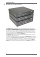
5 USB-ME-Systems 5.1 Setting Up and Connecting the USB-ME64-System USB-ME64-System is a high flexible system. Via MCS high grade cables it is possible to connect, for example, a MEA60-System or ME-Systems with at least 64 channels to the 64 analog inputs. Example: The description of the installation includes an example setup with a MEA1060 amplifier without blanking circuit. Warning: Please read the separate manuals of all devices before installation, especially the warnings and safety information.
USB-ME-System Manual 5.1.5 Rear Panel 5.1.6 Digital In / Out A Digital IN / OUT for 16 digital in- and output bits is available (68-pin MCS standard connector). The Digital IN / OUT connection accepts or generates standard TTL signals. TTL stands for Transistor-Transistor Logic. A TTL pulse is defined as a digital signal for communication between two devices. A voltage between 0 V and 0.8 V is considered as a logical state of 0 (LOW), and a voltage between 2 V and 5 V means 1 (HIGH).
Troubleshooting 5.1.9 Audio Output To the AUDIO OUT (3.5 mm phone jack) you can connect an audio system to make the electrical activity audible. By software control, it is possible to convert signals from one data channel into sound. A computer with a sound card and speakers or a headset is required. You can use this feature to hear Electrode Raw Data, for example, or to replay recorded sound. Or you can use an analog channel as a sound input and record any sounds.
USB-ME-System Manual 5.2 Setting Up and Connecting the USB-ME128-System USB-ME128-System is a high flexible system. Via MCS high grade cable it is possible to connect, for example, one MEA1060 amplifier or two MEA1060 amplifiers or a ME-Systems with at least 128 channels to the 128 analog inputs. Example: The description of the installation includes an example setup with a MEA1060 amplifier two MEA1060 amplifiers without blanking circuit.
Troubleshooting 5.2.5 Rear Panel 5.2.6 Digital In / Out A Digital IN / OUT for 16 digital in- and output bits is available (68-pin MCS standard connector). The Digital IN / OUT connection accepts or generates standard TTL signals. TTL stands for Transistor-Transistor Logic. A TTL pulse is defined as a digital signal for communication between two devices. A voltage between 0 V and 0.8 V is considered as a logical state of 0 (LOW), and a voltage between 2 V and 5 V means 1 (HIGH).
USB-ME-System Manual 5.2.9 Audio Output To the AUDIO OUT (3.5 mm phone jack) you can connect an audio system to make the electrical activity audible. By software control, it is possible to convert signals from one data channel into sound. A computer with a sound card and speakers or a headset is required. You can use this feature to hear Electrode Raw Data, for example, or to replay recorded sound. Or you can use an analog channel as a sound input and record any sounds.
Troubleshooting 5.3 Setting Up and Connecting the USB-ME256-System USB-ME-System is a high flexible system. Via MCS 68-pin high grade cables it is possible to connect, for example, four MEA60-Systems or two MEA120-Systems or a ME-System with at least 256 channels to the 256 analog inputs. Example: The description of the installation includes an example setup with four MEA1060 amplifiers without blanking circuit.
USB-ME-System Manual 5.3.1 Front Panel 5.3.2 Power LED The Power LED lights up when the USB-ME256 is connected via power supply unit to the power supply system. 5.3.3 Analog Inputs A, C, B, and D The 68-Pin MCS Standard connectors on the front panel of the device are analog inputs for the data streams coming from the connected amplifiers. The connectors on the left side of the front panel labeled with A and C communicate with the left digital Trigger Inputs 0 and 2.
Troubleshooting 5.3.5 Rear Panel 5.3.6 Digital In / Out A Digital IN / OUT for 16 digital in- and output bits is available (68-pin MCS standard connector). The Digital IN / OUT connection accepts or generates standard TTL signals. TTL stands for Transistor-Transistor Logic. A TTL pulse is defined as a digital signal for communication between two devices. A voltage between 0 V and 0.8 V is considered as a logical state of 0 (LOW), and a voltage between 2 V and 5 V means 1 (HIGH).
USB-ME-System Manual Warning: Do not use the SYNC IN and SYNC OUT to connect the USB-ME256 to any other device than another USB-ME-256. 5.3.9 Audio Output To the AUDIO OUT (3.5 mm phone jack) you can connect an audio system to make the electrical activity audible. By software control, it is possible to convert signals from one data channel into sound. A computer with a sound card and speakers or a headset is required.
Troubleshooting 5.4 External Power Supply The external power supply PS40W is used for all USB-ME-Systems. External power supply through: Plug in for the external power supply, for example, PS40W. The external power supply energizes the devices that are connected to the USB-ME256, for example, filter amplifier, gain amplifier or MEA amplifier with blanking circuit.
USB-ME-System Manual Troubleshooting 5.5 About Troubleshooting The following hints are provided to solve special problems that have been reported by users. Most problems occur seldom and only under specific circumstances. Please check the mentioned possible causes carefully when you have any trouble with the product. In most cases, it is only a minor problem that can be easily avoided or solved. If the problem persists, please contact your local retailer.
Troubleshooting 5.7 No Computer Connection / No Recording Possible You cannot establish a connection to the computer. The USB-ME-System channel layout is not available in MC_Rack. When loading a previously saved virtual rack file, you will get an error message and the simulator will be started automatically. Or you get an error message when starting the recording in MC_Rack after a successful computer connection. Possible causes: ? The power LED is not lightning.
USB-ME-System Manual 5.8 Cable Connection not correct / No Recording Possible You cannot establish a signal from the amplifier. The USB-ME-System channel layout in MC_Rack shows 50 Hz hum only. Possible causes: ? The cable connection from the computer to the periphery is not complete. 68-pin MCS standard connectors need to be fixed in the provided plugs by a firm connection. Otherwise no data transfer is possible. Check the MCS high grade cable, and the 68-pin MCS standard connectors.
6 Appendix 6.1 Contact Information Local retailer Please see the list of official MCS distributors on the MCS web site. User forum The Multi Channel Systems User Forum provides the opportunity for you to exchange your experience or thoughts with other users worldwide. Mailing list If you have subscribed to the mailing list, you will be automatically informed about new software releases, upcoming events, and other news on the product line.
USB-ME-System Manual 6.2 Scope of Delivery 24 1 USB-ME main device 1 USB 2.0 High Speed cable (type A - mini B) 1-7 Lemo coaxial cable with BNC and Lemo connectors (1 m) 1 Power cable: Lemo 4 mm connector 1 Power supply unit with country specific power cord 1 Data acquisition and analysis software MC_Rack (Version 3.6.3 or higher) 1 Data export software MC_DataTool (Version 2.4.
Index 6.3 Pin Layout Analog IN Pin Layout 68-Pin MCS Standard Connector A B C D Pin 1 GNDP (power ground) GNDP GNDP GNDP Pin 2 GNDS (signal ground) GNDS GNDS GNDS Pin 3 - 66 Channels 1 - 64 65 - 128 129 - 192 193 - 256 Pin 67 Pos. voltage supply Pos. voltage supply Pos. voltage supply Pos. voltage supply Pin 68 Neg. voltage supply Neg. voltage supply Neg. voltage supply Neg. voltage supply Galvanically isolated voltage supply and ground.
USB-ME-System Manual Digital IN / OUT Connector 68-Pin MCS Standard Connector Digital Out D0 26 Bit 0 of the 16 bit digital output channels (Pin 3) Pin 1 GNDP (power ground) Pin 2 GNDS (signal ground) Pin 3 - 10 Digital output channels bit 0 - 7 Pin 11 - 14 GNDS (signal ground) Pin 15 - 22 Digital output channels bit 8 - 15 Pin 23 - 26 GNDS (signal ground) Pin 27 - 34 Digital input channels bit 0 - 7 Pin 35 - 38 GNDS (signal ground) Pin 39 - 46 Digital input channels bit 8 - 15
Index 6.4 Technical Specifications The USB-ME-System is an Analog / Digital board converting analog signals in digital data streams in real-time. Warning: The device may only be used together with MEA-Systems or ME-Systems from Multi Channel Systems MCS GmbH, and only for the specified purpose. Damage of the device and even fatal injuries can result from improper use. Do not open the data acquisition box and do not change hardware configuration as it could lead to improper behavior of the system.
USB-ME-System Manual Interface and connectors Front panel 1 / 2 / 4 Digital Inputs Lemo connector, EPL.00.250 NTN 1 / 2 / 4 x 64 Analog In 68-pin MCS standard connectors, MCS high grade cable Rear panel 1 16 Bit Digital In / Out 68-pin MCS standard connectors, MCS high grade cable 1 Digital Out D0 Lemo connector, EPL.00.250 NTN 1 Sync In Lemo connector, EPL.00.250 NTN 1 Sync Out Lemo connector, EPL.00.250 NTN 1 Audio Output Stereo jack 3.5 mm, FFA.00.
Index 7 Index 29
USB-ME-System Manual 30
A Accessories O 24 B Bios settings 5 C Connecting the System 20 Connecting with a STG 20 Contact Information 23 Contact Pin Defective 20 F Front Panel 20 Analog Inputs ....................................20 Digital Trigger Inputs........................20 Power LED .........................................20 G Guarantee and Liability 2 Ordering Information 24 Accessories ........................................ 24 ME amplifiers .................................... 24 MEA amplifiers ..........
32