Temperature Controller TC01/02 Manual
Information in this document is subject to change without notice. No part of this document may be reproduced or transmitted without the express written permission of Multi Channel Systems MCS GmbH. While every precaution has been taken in the preparation of this document, the publisher and the author assume no responsibility for errors or omissions, or for damages resulting from the use of information contained in this document or from the use of programs and source code that may accompany it.
Table of Contents 1 1.1 Introduction About this Manual 1 1 2 2.1 2.2 2.3 Important Information and Instructions Operator's Obligations Important Safety Advice Guarantee and Liability 3 3 3 5 3 3.1 3.2 3.3 Installation and Operation Welcome to the Temperature Controller TC01/02 Setting Up and Connecting the TC01/02 Operating the TC01/02 3.3.1 Starting the TC01/02 3.3.2 General User Interface 3.3.3 TC01/02 Menus 3.3.4 Setting a Temperature 3.3.5 Channel Configuration 3.3.
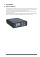
1 Introduction 1.1 About this Manual This manual comprises all important information about the first installation and the proper usage of the temperature controller TC01 and TC02. It is assumed that you have a basic understanding of technical terms, but no special skills are required to read this manual. Make sure you read the "Important Information and Instructions" prior to install or to operate this temperature controller.
2 Important Information and Instructions 2.
Temperature Controller TC01/02 Manual High Voltage Electrical cords must be properly laid and installed. The length and quality of the cords must be in accordance with local provisions. Only qualified technicians may work on the electrical system. It is essential that the accident prevention regulations and those of the employers' liability associations are observed. Each time before starting up, make sure that the mains supply agrees with the specifications of the product.
Important Information and Instructions 2.3 Guarantee and Liability The General conditions of sale and delivery of Multi Channel System MCS GmbH always apply. The operator will receive these no later than on conclusion of the contract. Guarantee and liability claims in the event of injury or material damage are excluded when they are the result of one of the following. Improper use of the device. Improper installation, commissioning, operation or maintenance of the device.
3 Installation and Operation 3.1 Welcome to the Temperature Controller TC01/02 Warning: Improper use, especially a too high setpoint temperature or an inappropriate channel configuration, for example, a too high maximum power, can lead to overheating the heating element. Overheating can lead to fire hazards and even fatal injuries. Only advanced users should edit the channel configuration and only with extreme care.
Temperature Controller TC01/02 Manual 3.2 Setting Up and Connecting the TC01/02 Provide a power supply in the immediate vicinity of the installation site. 1. Place the TC01/02 on a dry and stable surface, where the air can circulate freely and the device is not exposed to direct sunlight. 2. Plug the external power supply cable into the supply power input socket on the rear panel of the TC01/02. 3. Connect the external power supply to the power outlet. 4.
Installation and Operation 3.3 Operating the TC01/02 3.3.1 Starting the TC01/02 All functions are set in the menu of the TC01/02, including switching the TC01/02 on and off. If the TC01/02 is switched off, it goes into standby mode. The instrument and display are only switched off completely when the TC01/02 is disconnected from the power supply. Most of the power consumption of 6 W in standby mode is used by the power supply unit. In the main menu on the display, select On / Off.
Temperature Controller TC01/02 Manual 3.3.3 TC01/02 Menus Press the Select button to enter the Main menu. The other menu levels are shown in the following illustration. 3.3.4 Setting a Temperature Important: Please note that there will always be an intrinsic offset between the setpoint and the actual temperature of the connected heating element, depending on the heating element used, the proximity of the sensor to the heating element, and the experimental setup.
Installation and Operation Example: You are using a MEA1060-UP amplifier for upright microscopes on channel 1, and a perfusion cannula PH01 on channel 2 of a TC02. You have to configure each channel for the appropriate instrument. Select, for example, MEA2100 for channel 1 and PH01 for channel 2 in the Channel Configuration menu of the TC02. Note: The factory default parameters were optimized for an ambient temperature. The configuration for use with the PH01 were optimized for a medium flow rate.
Temperature Controller TC01/02 Manual Diagnosis 2: Controller settings This diagnose screen view is used for reviewing and checking the user settings. Setpoint Temp Setpoint temperature P Gain Proportional gain I Gain Integrator gain Max Power Maximum output power Diagnosis 3: Controller output This diagnose screen view is used for checking the operation of the internal controller. Power Set Output power set by the controller.
Installation and Operation 3.4 Controlling the TC01 / TC02 via TCX-Control Software Instead of configuring your TC01/02 via the front panel controls, you can also connect it to a PC with standard USB 2.0 cable and use the software TCX-Control. With this software, you can control all functions of one or more TC01/02 and it is also possible to read out the actual temperature values on your computer and save the data as a ".txt" file.
Temperature Controller TC01/02 Manual Two windows show the temperature on the two channels. The scaling of the y-axis is adjusted automatically. The x-axis shows the absolute time taken from the system clock. The scale of the time axis can be altered in the "Scale" drop down menu. Find in each channel window a "Power" button to activate and deactivate the respective channel. The status "Off / On" is displayed. If a channel is deactivated, the status "Off" is displayed above the "Power" button.
Installation and Operation With the "Export Data" option it is possible to start temperature logging retrospectively. When pressing the "Export Data" button, all data from the memory of the TCX-Control software up to the present time is exported to a file. Memory starts when the TCX-Control (NOT the channel) is turned on. The memory holds a maximum of 24 hours of data. If the TCX-Control software has been running more than 24 at the time the export function is used, only the last 24 hours will be saved.
Temperature Controller TC01/02 Manual These values can be saved to an ASCII file by pressing "Export diagnostics". The default settings for P and I coefficients and maximum power for the different devices can be modified under Device configuration. Use of the OP Table The OP Table consist of a heating plate for keeping the animal warm, and a rectal thermometer for measuring the body temperature of the animal. Both elements are equipped with a thermo sensor.
Installation and Operation Firmware Upgrade If you like to use a device from Multi Channel Systems MCS GmbH, which is not available in the settings of your temperature controller ( for example, the TCW1), you probably need to upgrade the software and the firmware, and you have to reset in the TCX. 1. Software: Install the appropriate software version (for example TCX-Control software Version 1.3.2 and higher). 2. Firmware: Click "Show extended information" in the main menu of the TCX-Control program.
4 Appendix 4.1 Control via Front Panel 4.1.
Temperature Controller TC01/02 Manual 4.1.
Index 4.1.
Temperature Controller TC01/02 Manual 4.2 D-Sub9 Pin Assignment Pins 1 to 4 of the female D-Sub9 input connector should be connected to the temperature sensor, and pins 7 and 8 to the heating element. The other three pins are not needed for operation. TC01 / TC02 : D-Sub Pin Assignment Note: A four-wire circuit is required for use with Pt100 sensors. Each of the two pairs assigned to pins 1/2 and 3/4 have to be connected together in close proximity to the PT100 sensor for proper operation.
Index 4.3 Parameter Ranges The setpoint temperature and the PI coefficients can be modified in the following ranges. The maximum power of the TCX is 30 W. If you connect a device with a maximum power less than 30 W, please decrease the maximum power to protect the device against destruction. 4.4 Parameter Range T 0.0 to 105.0 P 0.1 to 99.99 I 0.01 to 100.
Temperature Controller TC01/02 Manual 4.5 Technical Specifications Operating temperature Storage temperature 10 °C to 40 °C 0 °C to 50 °C Dimensions (W x D x H) 170 mm x 224 mm x 66 mm Weight 1.5 kg Supply voltage and current 24 V and 4 A Desktop AC Power Adapter 85 VAC to 264 VAC @ 47 Hz to 63 Hz Sensor type Pt 100 Measuring method four wire measuring bridge Measuring temperature range 0 °C to 105 °C Number of output channels 1 (TC01), 2 (TC02) Output voltage max.
Index 4.6 Contact Information Local retailer Please see the list of official MCS distributors (sales info) on the web site User forum The Multi Channel Systems User Forum provides the opportunity for you to exchange your experience or thoughts with other users worldwide. News Letter If you have subscribed to the newsletter, you will be automatically informed about new software releases, upcoming events, and other news on the product line. You can subscribe to the list on the MCS web site. www.
Temperature Controller TC01/02 Manual 5 Index 26
Index 27
C P Channel configuration 9 Integrator gain....................................9 maximum power .................................9 proportional gain................................9 Parameter Ranges G S General user interface 9 Back......................................................9 Select....................................................9 UP / DOWN ..........................................9 Setting a temperature Guarantee and Liability 4 H Hardware diagnosis 7, 9 controller output .........
29