Temperature Controller TC01/02 Manual
Information in this document is subject to change without notice. No part of this document may be reproduced or transmitted without the express written permission of Multi Channel Systems MCS GmbH. While every precaution has been taken in the preparation of this document, the publisher and the author assume no responsibility for errors or omissions, or for damages resulting from the use of information contained in this document or from the use of programs and source code that may accompany it.
Table of Contents Introduction About this Manual 1 1 Important Information and Instructions Operator's Obligations Important Safety Advice Guarantee and Liability 3 3 4 3 Installation and Operation Welcome to the Temperature Controller TC01/02 Setting Up and Connecting the TC01/02 Operating the TC01/02 Starting the TC01/02 General User Interface TC01/02 Menus Setting a Temperature Channel Configuration Hardware Diagnosis Controlling the TCX via USB Port 7 7 8 8 8 9 10 11 11 12 14 Appendix D-Sub9 Pin A
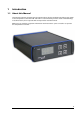
1 Introduction 1.1 About this Manual This manual comprises all important information about the first installation and the proper usage of the temperature controller TC01 and TC02. It is assumed that you have a basic understanding of technical terms, but no special skills are required to read this manual. Make sure you read the "Important Information and Instructions" prior to install or to operate this temperature controller.
2 Important Information and Instructions 2.
Temperature Controller TC01/02 Manual 2.3 Important Safety Advice Warning: Make sure to read the following advice prior to install or to use the device and the software. If you do not fulfill all requirements stated below, this may lead to malfunctions or breakage of connected hardware, or even fatal injuries. Warning: Obey always the rules of local regulations and laws. Only qualified personnel should be allowed to perform laboratory work.
Important Information and Instructions Requirements for the installation and operation Warning: Improper use (especially a too high setpoint temperature or an inappropriate channel configuration, for example, a too high maximum power) can lead to overheating the heating element. Overheating can lead to fire hazards and even fatal injuries. Only advanced users should edit the channel configuration and only with extreme care. Make sure that the device is not exposed to direct sunlight.
3 Installation and Operation 3.1 Welcome to the Temperature Controller TC01/02 Warning: Improper use, especially a too high setpoint temperature or an inappropriate channel configuration, for example, a too high maximum power, can lead to overheating the heating element. Overheating can lead to fire hazards and even fatal injuries. Only advanced users should edit the channel configuration and only with extreme care.
Temperature Controller TC01/02 Manual 3.2 Setting Up and Connecting the TC01/02 Provide a power supply in the immediate vicinity of the installation site. 1. Place the TC01/02 on a dry and stable surface, where the air can circulate freely and the device is not exposed to direct sunlight. 2. Plug the external power supply cable into the supply power input socket on the rear panel of the TC01/02. 3. Connect the external power supply to the power outlet. 4.
Installation and Operation 3.3.2 General User Interface The display shows the actual temperature and the setpoint temperature. You can enter the next menu levels by pressing the Select button. Go to a menu command with the Up and Down buttons and press Select to select the command highlighted by an arrow and to enter the next menu level. The functionality of the button array on the front panel is described in the following. Up Goes to the menu command above or increases the displayed parameter value.
Temperature Controller TC01/02 Manual 3.3.3 TC01/02 Menus Press the Select button to enter the Main menu. The other menu levels are shown in the following illustration.
Installation and Operation 3.3.4 Setting a Temperature Important: Please note that there will always be an intrinsic offset between the setpoint and the actual temperature of the connected heating element, depending on the heating element used, the proximity of the sensor to the heating element, and the experimental setup. This offset needs to be determined empirically and taken into account when programming the temperature settings.
Temperature Controller TC01/02 Manual 3.3.6 Hardware Diagnosis This menu should be used for reviewing parameter settings or check the hardware performance in case that you observe any trouble with the instrument. Each channel can be checked separately. If the problem persists, please contact your local retailer. The highly qualified staff will be glad to help you. Keep the displayed information at hand when contacting customer support.
Installation and Operation Diagnosis 4: Heating element This diagnose screen view is used for checking the connected heating element.
Temperature Controller TC01/02 Manual 3.4 Controlling the TCX via USB Port Instead of configuring your TC01/02 via the front panel controls, you can also connect it to a PC with standard USB cable and use the software TCX-Control. With this software, you can control all functions of one or more TC01/02 and it is also possible to read out the actual temperature values on your computer and save the data as a ".txt" file.
Installation and Operation If a channel is deactivated, the status Off is displayed above the Power button. Additionally the status Off is displayed in red letters in the Setpoint drop down menu in exchange for the setpoint temperature. The actual temperature is displayed as a number and plotted against time. There is also a selection field to adjust the Setpoint temperature. Under the Select device drop down menu, it is possible to select the type of instrument connected to the respective channel.
Temperature Controller TC01/02 Manual 3.4.2 Extended Information It is possible to display the extended information with all parameters from the TC01/02. Click Show extended information in main menu. These values can be saved to an ASCII file by pressing Export diagnostics. The default settings for P and I coefficients and maximum power for the different devices can be modified under Device configuration.
Installation and Operation Firmware Upgrade If you like to use a device from Multi Channel Systems MCS GmbH, which is not available in the settings of your temperature controller ( for example, the TCW1), you probably need to upgrade the software and the firmware, and you have to reset in the TCX. 1. Software: Install the appropriate software version (for example for TCW1, TCX-Control software Version 1.1.9 and higher). 2.
4 Appendix 4.1 D-Sub9 Pin Assignment Pins 1 to 4 of the female D-Sub9 input connector should be connected to the temperature sensor, and pins 7 and 8 to the heating element. The other three pins are not needed for operation. TC01 / TC02 : D-Sub Pin Assignment Note: A four-wire circuit is required for use with PT100 sensors. Each of the two pairs assigned to pins 1/2 and 3/4 have to be connected together in close proximity to the PT100 sensor for proper operation.
Temperature Controller TC01/02 Manual 4.3 MCS Default PI Coefficients Note: The following PI parameters have been optimized at an ambient temperature of 25 °C, the PI coefficients for use with the PH01 at a flow rate of 3 ml/min. You may have to adjust these PI coefficients for your experimental setup, especially if the ambient temperature or the flow rate differ at large from those used by MCS.
Appendix 4.5 Contact Information Local retailer Please see the list of official MCS distributors (sales info) on the web site User forum The Multi Channel Systems User Forum provides the opportunity for you to exchange your experience or thoughts with other users worldwide. News Letter If you have subscribed to the newsletter, you will be automatically informed about new software releases, upcoming events, and other news on the product line. You can subscribe to the list on the MCS web site. www.
5 Index 23
Temperature Controller TC01/02 Manual 24
C P Channel configuration 8 Integrator gain....................................8 maximum power .................................8 proportional gain................................8 Parameter Ranges G S General user interface 8 Back......................................................8 Select....................................................8 UP / DOWN ..........................................8 Setting a temperature Guarantee and Liability 4 H Hardware diagnosis 7, 8 controller output .........
26