Stimulus Generator Manual STG 4004 and STG 4008
Information in this document is subject to change without notice. No part of this document may be reproduced or transmitted without the express written permission of Multi Channel Systems MCS GmbH. While every precaution has been taken in the preparation of this document, the publisher and the author assume no responsibility for errors or omissions, or for damages resulting from the use of information contained in this document or from the use of programs and source code that may accompany it.
Table of Contents 1 1.1 1.2 1.3 Introduction About this Manual Terms of Use for MC_Stimulus II Limitation of Liability 1 1 2 2 2 2.1 2.2 2.3 Important Information and Instructions Operator's Obligations Guarantee and Liability Important Safety Advice 3 3 3 4 3 3.1 3.2 3.3 3.4 First Use of the Stimulus Generator Welcome to the STG and MC_Stimulus Setting Up and Connecting the STG Driver Installation Installing the Software 5 5 8 9 10 4 4.1 4.
Stimulus Generator 4000 Series Manual 8 8.1 iv 8.2 Downloading Stimuli Downloading Stimulus Files 8.1.1 Download Modes 8.1.2 Independent Channel Download Operating multiple MEA Amplifiers with one STG 49 49 49 50 51 9 9.1 9.2 9.3 9.4 9.5 9.6 General Software Features Customizing the Main Window Menu Bar Toolbar Shortcut Keys File Menu Settings Menu 53 53 53 54 54 55 56 10 10.1 10.2 10.3 10.4 10.5 10.
1 Introduction 1.1 About this Manual This manual comprises all important information about the installation and operation of the stimulus generator STG4000 series and MC_Stimulus II software. It is assumed that you have already a basic understanding of technical and software terms. No special skills are required to read this manual. This documentation refers only to the STG hardware and MC_Stimulus II software.
Stimulus Generator 4000 Series Manual 1.2 Terms of Use for MC_Stimulus II You are free to use MC_Stimulus II for its intended purpose. You agree that you will not decompile, reverse engineer, or otherwise attempt to discover the source code of the software. 1.3 Limitation of Liability Multi Channel Systems MCS GmbH makes no guarantee as to the accuracy of any and all tests and data generated by the use the MC_Stimulus II software.
2 Important Information and Instructions 2.
Stimulus Generator 4000 Series Manual 2.3 Important Safety Advice Warning: Make sure to read the following advice prior to install or to use the device and the software. If you do not fulfill all requirements stated below, this may lead to malfunctions or breakage of connected hardware, or even fatal injuries. Warning: Obey always the rules of local regulations and laws. Only qualified personnel should be allowed to perform laboratory work.
3 First Use of the Stimulus Generator 3.1 Welcome to the STG and MC_Stimulus Product line overview Stimulus generators of the 4000 series are general purpose stimulators designed for a wide variety of applications, both in vitro and in vivo. Flexible and easy-to-use MC_Stimulus software enables complex stimulus waveforms (both current and voltage).
Stimulus Generator 4000 Series Manual 4000 Series The real-time stimulus generator of the 4000 series is an advanced version and the world's first STG that is able to send continuous pulse streams to stimulating electrodes. In addition, you can trigger all (up to 8) channels separately by external TTL pulses. 2 trigger inputs (Trigger In) and 2 trigger outputs (Sync Out) are shared by 2 channels in the 2-channel version.
First Use of the Stimulus Generator MC_Stimulus II Stimuli are created user-friendly by entering the desired pulses (rectangular, ramp, or sine waveforms) into a worksheet. Waveforms can be combined freely to create virtually any stimulus pattern. Created stimuli are displayed in a WYSIWYG stimulus display. All channels are set up separately. For even more convenience, repetitive stimulus patterns do not have to be entered separately, but can be grouped and looped.
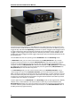
Stimulus Generator 4000 Series Manual 3.2 Setting Up and Connecting the STG Note: You can use a USB hub for connecting the STG to the computer, for example, if you have no free USB port or if you need to extend the USB cable.
First Use of the Stimulus Generator Illustration of the STG 4000 series front and rear panel with connectors STG 4004 Front Panel STG 4004 Rear Panel STG 4008 Front Panel STG 4008 Rear Panel 3.3 Driver Installation The stimulus generator is a plug and play device. The driver is automatically installed together with the MC_Stimulus II program. The Windows operating system detects a new hardware when the stimulus generator is connected to the computer, if the program has not been installed beforehand.
Stimulus Generator 4000 Series Manual 3.4 Installing the Software System requirements Software: One of the following Microsoft Windows ® operating systems is required: Windows 7, Vista or Windows XP (English and German versions supported). Hardware: USB port (2.0 High Speed) Installing the software Please check the system requirements before you install the software. MCS cannot guarantee that the software works properly if these requirements are not fulfilled.
4 Operating the STG 4.1 Operation Overview Warning: Make sure that you do not come in contact with the cables or the connectors of the STG after you have started the STG. The high voltage and power can lead to injuries. Warning: Do not start the STG if you are unsure about the channel configuration or the nature of the downloaded file. 1. Set up your experiment. 2. Switch the STG on. Note: It is recommended to start the STG ten minutes before use to allow warming up! 1.
Stimulus Generator 4000 Series Manual STG interface: You can start the stimulation by pressing the Start / Stop button on the front panel of the STG. Press the button again to stop the stimulation. Starting the STG by pressing the Start / Stop button is considered as activating all four trigger inputs, that is, all channels are started and stopped, and all four Sync Out outputs are active when the STG is started.
Operating the STG STG and Stimulus Protocol Information: Autocalibration During the first ten minutes after starting the STG, the device emits every minute high frequency signals (small bursts) for internal offset calibration of the current outputs in a range of +/- 10 mV. After warming up the STG, the calibration signals later will be delivered half-hourly.
Stimulus Generator 4000 Series Manual 4.2 Operating Multiple STGs If you have more than one STG connected to the same computer, please click under "STG" in main menu "Select Device". In the "Select Device" dialog you can choose which STG you like to control from the currently active MC_Stimulus II program. The serial number is printed on the STG's case. The serial number of the currently active STG is displayed on the status bar of the currently active instance of the MC_Stimulus II program.
Operating the STG 4.2.1 Operating the USB-MEA32-STIM4-System The USB-MEA32-STIM4-System has an integrated four channel current stimulus generator. For operating this kind of STG, please select the device in Select Device dialog via serial number. To select stimulation channels, open the dialog Select Stimulation Channels in Edit menu. Select Layout: 1 x 12. It is possible to assign stimulation channel 1 and 2 to stimulation electrodes S1 to S6.
5 Programming Stimulus Protocols 5.1 MC_Stimulus II Sample Files for STG 4000 Series These sample files are intended for demonstrating basic features of the Stimulus Generator STG 4000 series, for basic applications with the MEA-System. If you are using an MEA-System, please see also the MC_Rack tutorial in the MC_Rack help or the separate PDF on the installation volume. The sample files are automatically installed to the Examples folder in the MC_Stimulus II program directory.
Stimulus Generator 4000 Series Manual monophasic_voltage_1V_100μs.stm Stimulus type: Monophasic test pulse Amplitude: 1 V Duration: 100 µs Inter-Stimulus-Interval: 24 ms biphasic_voltage_1V_100μs.stm Stimulus type: Biphasic test pulse Amplitude: 1 V Duration: 100 µs per phase Inter-Stimulus-Interval: 24 ms ASCII-Import-Biopotential.stm This file is not intended for a real experiment, but demonstrates the ASCII import feature.
Programming Stimulus Protocols 5.3 MC_Stimulus II Worksheet You can freely combine any pulse types. Use a separate row for each pulse type. Hint: Several tools are provided for editing whole columns at once or autocreating entries. 1. Select the desired output type first. Click either Voltage or Current under Output Mode on the file window of MC_Stimulus. 2. Click a tab to select an output channel. The according channel worksheet is brought to front. 3. Now you can enter the pulses into the worksheet.
Stimulus Generator 4000 Series Manual 5.4 Pulse Types Three basic pulse types are available in MC_Stimulus II. You can create virtually any pulse by combining different types. Rectangular Ramp Sine wave Note: The time resolution is 20 μs. When you enter time steps that are not a multiple of 20 μs, the length of the step is internally adjusted (rounded arithmetically, that is, 249 μs would be rounded down to 240 μs, 250 would be rounded up to 260 μs) to a valid value.
Programming Stimulus Protocols Ramp pulse type Define the starting point, end point, and the length of the ramp. The ramp is then build according to these parameters in small single steps of 20 μs. Sine wave pulse type Define the amplitude and the period of the sine wave. The sine wave is then computed according to these parameters with a minimum resolution of 1 mV and 20 μs. If you enter a negative amplitude, the sine wave starts with its negative alternation.
Stimulus Generator 4000 Series Manual 5.5 Autorepeating Pulses and Protocols For entering complex stimuli easier and faster, you can repeat rows and groups instead of entering the pulses several times into the worksheet. You can repeat each single row. In the preceding example, the rectangular pulse in row 1 is repeated twice. You can also group several rows and repeat them altogether. In the example, pulses from rows 1 to 4 are grouped and repeated three times.
Programming Stimulus Protocols 4. Type the number of repeats into the merged Group Repeat cell. Repeating complete pulse protocols (autorepeat function), Continuous Mode You can repeat the complete stimulus on all output channels that are triggered by the same trigger. This means, each time when a trigger event occurs, the complete stimuli on all corresponding output channels are repeated for the specified number of times. If the stimuli have different lengths, the starting points are synchronized.
Stimulus Generator 4000 Series Manual In the following example, the stimuli on output channels 1, 3, and 6 that are all triggered by Trigger 1 are repeated three times after the trigger event, each time accompanied by the Sync Out 1 output. All other stimuli are applied once after their respective trigger event. Repeating complete pulse protocols, Gating Trigger Repeated stimulation of complete protocols can also be controlled by a gating trigger.
Programming Stimulus Protocols 5.6 Autocreating Entries and Editing Columns Changing time units for a complete column 1. Click any Unit column header to select a column. The selected column is highlighted in black. 2. Right-click and click Change Time Unit. 3. Select the desired time unit. All units in the column are set to the selected time unit. Inverting pulses in a column 1. Click any Value column header to select a column. The selected column is highlighted in black.
Stimulus Generator 4000 Series Manual 2. Right-click and click Invert Selection. The polarity of the signals is switched from positive to negative and vice versa. Incrementing columns This feature is very convenient for setting up long and complex stimuli without entering each value manually. You can enter and edit multiple voltage values or time lengths. You can keep all zero values unchanged with the option Keep Zero.
Programming Stimulus Protocols 2. Right-click and click Increment Selection. 3. Under Type of Increment, select Shift. 4. Enter the desired value. All values in the selected column are modified by the selected factor. In the example, 100 is added to all values, resulting in a total of 100 because the initial value has been 0.
Stimulus Generator 4000 Series Manual Creating time or voltage / current increments With this option, you enter a base value for modification of all values in the selected column. The first row is modified by the base value. The second row is modified by the double value, the third row by thrice the base value, and so on. With this feature, you can easily set up time or voltage increments. 1. Under Type of Increment, select Count. 2. Enter the desired start value.
Programming Stimulus Protocols You can now fill further columns in the same way. Thus, you can easily set up a stimulus with incremented pulse lengths like this with only a few mouse-clicks. In the same way, you can set up a stimulus with voltage / current increments. Shifting absolute time or voltage values With this option, the signs of the selected values are ignored. Zeros are never changed, that is, the option Keep Zero cannot be deselected. 1. Under Type of Increment, select Absolute Value. 2.
Stimulus Generator 4000 Series Manual The absolute values of 200 and 200 are both 200. This absolute value of -200 is modified by the shift factor of 50, resulting in 250. The negative value is now 250, and the positive value is 200. (If you had chosen the option Shift instead, the computed result would have been 200 + 50 = 250.) All zero values are not changed. Autocreating entries You can use the Autofill feature to set up advanced time or voltage/current increments.
Programming Stimulus Protocols The column is filled according to the specifications. 5.7 Auto Sync for Autocreating Trigger Pulses If you want to synchronize other devices, for example, a MEA1060-BC amplifier or the MC_Card with the stimulus generator, you have to set up the digital output of the Sync Out channels in synchrony to the stimulus pulses. This may sometimes be a bit tricky and time consuming, especially for complex stimulus protocols.
Stimulus Generator 4000 Series Manual 2. Assign the analog stimulus channels that will be used as the basis for autocreating the protocols on the Sync Out channels 1 to 4. For example, if you use only stimulus channel 1, select Ch1 under Sync1. If you use a MEA1060-BC amplifier, you can use up to two output channels per amplifier, that is, you may want to select Ch1 and Ch2 for Sync1.
Programming Stimulus Protocols 2. Select the option Auto Download if you want to adjust the stimulus intensity level on-the-fly. Deselect the option if you want to download the changes manually later. 3. Select the option Change All if you want to adjust the stimulus intensity to the same level on all channels. Deselect the option if you want to set individual channels to different levels. 4.
6 ASCII Import / Export 6.1 Loading Files The ASCII import filter is used to load stimulus protocols from an ASCII file into the stimulus worksheet of MC_Stimulus II. You can use this feature for feeding recorded signals (for example, exported from MC_Rack, see the MC_Rack manual) into the stimulus generator. You can also export the data from MC_Stimulus, modify it with your custom text or spreadsheet editor, and reimport it into MC_Stimulus II. The current version of the import filter is version 3.1.
Stimulus Generator 4000 Series Manual 6.2 Exporting Files 1. On the File menu, click Export ASCII File. The Save As dialog box appears. 2. Browse to the target folder and enter a file name. 3. Click Save to generate the ASCII file. All pulse protocols from the active file will be saved in ASCII file format. The MC_Stimulus II ASCII format type is format type 4. For your convenience, the generated ASCII file includes the header that is required for reimporting the file into MC_Stimulus II. 6.
ASCII Import/Export Example: You have to include the following line in the ASCII file if you have installed MC_Stimulus II for STG2004. channels: 4 Output mode is either voltage or current. Example: output mode: voltage Six different format types are available: 1, 2, 3, 4, 5, 6. Example: format: 3 Data Preceding the data, the output channel number has to be specified by the following line.
Stimulus Generator 4000 Series Manual Format type 1 This is a basic format with two columns of Value and Time each, without Repeat functionality. value time value time Format type 2 With this format, you can repeat rows in the same way as described for the worksheet. Group repeat is not available. value time value time repeat Format type 3 This format type is available only in the current version of the import filter. It allows you to use a third column of Value and Time.
ASCII Import/Export The same file would look like this in a standard text editor program. You can see the tabs, spaces, and CR / LF. After loading the file into the MC_Stimulus II worksheet, you can edit and download the file as usual.
Stimulus Generator 4000 Series Manual Format type 4 This format type is available only in the current version of the import filter. It is the plainest format with only one column for the voltage / current values and one column for the time lengths. This format is the standard format if you want to import data for example from Excel. This format type is generated when exporting MC_Stimulus II files as ASCII.
ASCII Import/Export Example: This is an ASCII file viewed in a standard text editor program. You can see the tabs, spaces, and CR / LF. For demonstration purposes, a ramp type pulse was programmed on the first channel, a sine wave on the second channel, a rectangular waveform on the third channel, and mixed pulse types on the fourth channel.
Stimulus Generator 4000 Series Manual After loading the file into the MC_Stimulus II worksheet, you can edit and download the file as usual. Format type 6 Note: This file format is used by MC_Rack ASCII export! This format type is available only in the current version of the import filter. This is a basic format with two columns: The absolute time in seconds, and the absolute value of voltage in microvolts (μV) or current in microamper (μA). This file format is used by MC_Rack ASCII export.
ASCII Import/Export The following picture shows a file of format type 6 with header. Using the format type 6 without header, only the first channel of the MC_Rack raw data file can be imported. Using the format type 6 with header you choose how many channels are imported in "channels", line 3. The output mode in line 4 has to be voltage. You choose which channel should be imported first in "channels" line 6. You can add the channels you also want to import one after the other in any order.
Stimulus Generator 4000 Series Manual ASCII Import of Files For ASCII import of files, please use the command ASCII Import in main menu "Settings". The dialog "ASCII Import Settings" will open. Settings for ASCII import files without header: Select the format type from one to six from the drop down menu "Format". Select the number of the row from which the file should be imported. Row numbers are available from one to ten from the drop down menu "From row".
7 Stimulus Display 7.1 Selecting Channels To enlarge the display size of the channels, we suggest that you show only those channels you are currently working with. Note: This will affect only the display. It has no effect on the download of signals. To select or deselect channels for downloading, click the Download Channel (or Download Sync) check boxes in the main window of the program. Clear the check box of all channels that are not in use.
Stimulus Generator 4000 Series Manual Enable scrolling Scroll the axes by clicking and dragging with your mouse. Enable scaling Zoom the axes by clicking and dragging with your mouse. Zoom out Reduces the time scale. Zoom in Magnifies the time scale. Reset Resets the axes of all channels to the default values. Size to fit Adjusts the ranges to fit the largest displayed stimulus.
Stimulus Display Zooming the display 1. Click to enable the scaling. 2. 2. Click the axis you like to scale. The mouse pointer becomes an arrow. 3. While holding down the mouse button, move the mouse up/right to zoom the axis in, and move the mouse down/left to zoom the axis out. - OR You can use the keyboard: Press LEFT ARROW or DOWN ARROW to zoom the axis out, RIGHT ARROW or UP ARROW to zoom the axis in.
8 Downloading Stimuli 8.1 Downloading Stimulus Files After having set up the stimulus file, you can download the file to the connected STG. You can select the channels that you want to download or download the complete file. You can start the stimulation directly after the download, or start it manually with the software or hardware controls, or start it on a trigger. See also chapter "Operating the STG" for more information. Warning: Check the file thoroughly before downloading it on the STG.
Stimulus Generator 4000 Series Manual Independent Channel Download The second option is to use the feature “Independent Channel Download” which is available in the Settings menu. This feature allows downloading a new stimulation paradigm to individual channels only, while all other channels continue with their former program without stopping. To allow this, the memory space of the STG is divided among all available channels.
General Software Features The following dialog appears when you change anything in the “Trigger Settings” dialog. Click “Yes” button to download on all channels, click “No” button to download on selected channels. 8.2 Operating multiple MEA Amplifiers with one STG It is possible to operate more than one MEA amplifier independently with a single stimulus generator of the 4000 series. To do this, activate the Independent Channel Download feature in the Settings menu.
Stimulus Generator 4000 Series Manual To download a stimulation paradigm to individual channels assigned to one amplifier only, select all channels connected to this amplifier in the “Download Channel” check box (1 and 2 in this example) and Sync Out 1 in “Download Sync” check box, whether you changed them all or not! Only these channels will be downloaded, ongoing stimulation on other channels will not be interrupted.
General Software Features 9 General Software Features 9.1 Customizing the Main Window You can customize the size and position of open file windows and the toolbar in MC_Stimulus II. You can hide the toolbar and the status bar by deselecting them on the View menu. You can arrange the windows with the commands on the Window menu. Cascade: Use this command to arrange multiple opened windows in an overlapped fashion. The windows are resized to the standard size.
Stimulus Generator 4000 Series Manual 9.3 Toolbar For your convenience, you will find some of the more commonly used commands as a button on the toolbar. 9.4 New File Creates a new MC_Stimulus II file (*.stm) file. Open File Opens a previously saved MC_Stimulus II file (*.stm) file. Save File Saves the *.stm file to the chosen destination. Cut Row Deletes selected row(s) and sends deleted row(s) to clipboard. Copy Row Sends selected row(s) to clipboard.
General Software Features Hint: Shortcut key combinations are also listed on the toolbar menus. For example, the File menu shows that the shortcut key for Save is CTRL+S. 9.5 File Menu You can save MC_Stimulus II files for later use. This is very convenient if you have various similar experimental setups, or if you like to repeat an experiment later. Open a file You may open previously saved files for similar experimental setups. 1. On the File menu or on the toolbar, click Open . 2.
Stimulus Generator 4000 Series Manual 9.6 Settings Menu Enable Compiler Warnings Cancel this option to disable the message boxes displaying compiler warnings during stimulus download. The two error messages that can be disabled are: "warning: signal length shorter than the maximum" and "warning: non zero last amplitude value". They may present a nuisance if you download multiple stimulus files in batch mode, or if you want to adjust the stimulus intensity level on the fly.
10 Synchronizing Events 10.1 Digital Output Signals (Sync Out) The output of the digital Sync Out outputs is a 3.3 V TTL signal. A logic state of 1 means 3.3 V, and a logic state of 0 means 0 V. Please note that the digital output is about 15 μs faster than the analog output. This small offset is generally sufficient to make sure that the Sync Out signal precedes the stimulation, which is important for synchronizing events.
Stimulus Generator 4000 Series Manual The following example shows a blanking signal (programmed with MC_Stimulus II) of 300 μs length for a biphasic pulse of 200 μs length. See also the MEA_Select help or the “MEA Amplifier with Blanking Circuit” manual for more information. You can use the Auto Sync feature for autocreating the Sync Out pulses without entering values manually. Please see "Auto Sync for Autocreating Synchronous Sync Out Pulses". 10.
Synchronizing Events You can start and stop the trigger manually at any time using the LED Start / Stop buttons. Custom switch for "remote-controlling" of the STG You can connect any device that produces TTL outputs to the Trigger In connector of the STG, for example a switch. For example, you can use a trigger for remote controlling the STG if it is not within reach during an experiment.
Stimulus Generator 4000 Series Manual 10.3 Trigger Settings Triggering output channels (Standard mode) You can use up to four or eight separate trigger inputs for triggering up to four or eight output channels (STG4004 or STG4008, respectively). The trigger settings are saved in the currently active MC_Stimulus II (*.stm) file. Please assign the four triggers to the analog output channels in the Trigger Settings dialog box in the Edit menu.
Synchronizing Events Triggered action when channel(s) still active You can define what action should be taken when any of the channels assigned to the trigger are still active. Please click the expand button to show the advanced options: Stop: A following trigger input stops the stimulation on the assigned channels if at least one channel that has been assigned to this particular trigger is still active in the moment of the trigger event.
Stimulus Generator 4000 Series Manual Select “Single Trigger” if you want to start the stimulus protocol once via external trigger. Set up your stimuli with the MC_Stimulus II program. Download the stimulus protocol from a MC_Stimulus II file to the STG. Arm the STG either manually by pressing the Start / Stop button on the front panel, or with software controls. To arm the STG via software, use the start icon in MC_Stimulus II main menu, or click the combined LED / Start / Stop button for the “Sweeps”.
Synchronizing Events 10.4 Multi File Mode As an alternative to triggering separate channels in a single stimulus protocol, you can also trigger up to four separate stimulus files in the Multi-File mode. This feature allows you to trigger different stimulus protocols on overlapping channels. For example, you can control stimulus pattern A by trigger 1 on channels 1 and 2, and stimulus pattern B by trigger 2 on channels 2 and 3, and so on.
Stimulus Generator 4000 Series Manual 8. Check all stimulus protocols before download. Please make sure that you have selected all necessary channels under Download Channel for each file separately. 9. Download the files onto the STG by clicking Download on the STG menu. 10. The stimulation as specified in the selected MC_Stimulus files will now be triggered by the selected trigger inputs (Trigger In 14).
Synchronizing Events Assignment of the digital inputs D7 to D0: The user is asked to compose his own stimulation pattern files. Please do not create too big stimulus files, because all files are completely downloaded, and stored in the memory of the STG. If the files contain too much data, and you apply a lot of files, you will get an error message on download.
Stimulus Generator 4000 Series Manual Please make sure to use the correct format. 1. Connect the digital IN /OUT connector to a TTL signal source. 2. Ground digital inputs manually which are not used. 3. Set up your own stimulus protocols, either nine stimulus patterns or up to 256 patterns, and save the files. 4. On the Edit menu, click Trigger Settings. 5. Select the option Extended Multi-File. 6. Optionally select the check box "Show all Patterns". 7.
Synchronizing Events 10.6 Batch Mode You can download and run several stimulus files one after the other in the Batch mode. The first file in the list is downloaded and started directly after the download, or started manually with the software or hardware controls, or started on a trigger. After the first file has been run, the next file in the list is downloaded, and so on, until the last file in the batch list has been run.
Stimulus Generator 4000 Series Manual Operating the STG in Batch mode Important: You can operate the STG in Batch mode only with a valid computer connection. A file in the batch list is only downloaded after the preceding file has been run. 1. On the Batch menu, click Open to open a batch file. The Open dialog box appears. 2. Browse your folders and select a valid batch file, for example the sample file TetanusBatch.stb in the MC_Stimulus II program folder. 3. The Batch Status Display opens.
11 Analog Output Signals 11.1 Output Modes The stimulus generator operates in voltage and current mode. Choose voltage or current mode in the main window of MC_Stimulus II. Please make sure that you use the appropriate stimulation mode for your experiment. The difference between current and voltage controlled stimulation is described in the following.
Stimulus Generator 4000 Series Manual 11.2 Voltage Mode If you want to operate the STG in voltage mode, you have to select "Voltage" in Output Mode of the main window of MC_Stimulus II. You will usually use the + and GND outputs. The output signal is identical with the programmed signal in the normal ranges of the electronics' accuracy. See illustration "Voltage mode: Standard Setup". The output signals are inverted (multiplied by -1) if you use the - outputs.
Analog Output Signals STG output signals: 71
Stimulus Generator 4000 Series Manual Screen shot from a standard oscilloscope triggered on the Sync Out pulse (see "Measuring output signals with an oscilloscope"). Green trace = voltage output (+U), red trace = inverted voltage output (-U), pink trace = TTL output from the Sync Out. Voltage output 1 V and Sync Out.
Analog Output Signals 73
Stimulus Generator 4000 Series Manual 11.3 Current Mode If you want to operate the STG in current mode, you have to select "Current" in Output Mode of the main window of MC_Stimulus II. You will usually use the + and GND outputs. See illustration "Standard setup". The output signals are inverted (multiplied by -1) if you use the - outputs. If the load resistance, that is, the electrode impedance is very high, the output voltage can get very high, too.
Analog Output Signals Current output 200 μA and Sync Out. The time lag between the Sync Out output and the current output is approximately 15 μs (+/- 2 μs) if continuous mode is enabled and 50 μs (+/- 2 μs) if continuous mode is disabled. Setup suggestions for current mode The following illustrations show circuit diagrams of suggested setups. Please note that for current stimulation, you should use shielded cables to protect your setup against electromagnetic interference.
Stimulus Generator 4000 Series Manual 76
Analog Output Signals 11.4 Measuring Output Signals with an Oscilloscope For test purposes, you can measure the output signals with an oscilloscope. Please see the appendix for the pin layout of the sockets on the front panel of the STG4000 series. Most standard oscilloscopes have a probe with a ground cable. This probe is usually connected to the oscilloscope via a BNC socket.
Stimulus Generator 4000 Series Manual Amplitude dependency of rise time The rise time is independent from the current amplitude in the common range of amplitudes.. The rise time (10 % /90 %) was measured with increasing current amplitudes (100 μA to 1600 μA) and a constant load resistance of 10 k. The output current is nearly constant up to amplitudes of 1100 μA, but increases about 0.3 μs until the maximum of 1600 μA amplitude is reached. The relationship is not linear as shown by the following curve.
Analog Output Signals The graphs were generated by a standard oscilloscope. The devices were set up according to the recommendations under "Voltage Mode" and "Current Mode". The same pulse protocol and the same channel number of the STG outputs were used for measuring the voltage and the current output.
Stimulus Generator 4000 Series Manual Example 1b: Current Mode: The green trace shows the current output (+I) with a load resistance of 10 k; and the pink trace shows the TTL output from the Sync Out that was used for triggering the oscilloscope Rise time with programmed 500 mV and 50 μA pulses, 10 k load resistance. Rise time (10 % / 90 %) = 3 μs Result of Example 1: The rise time is about 3 μs for the 500 mV voltage pulse, and about 3 μs for the 50 μA current pulse.
Analog Output Signals Example 2a: Voltage Mode: The green trace shows the voltage (+U) output; and the pink trace shows the TTL output from the Sync Out that was used for triggering the oscilloscope Rise time with programmed 5 V and 500 μA pulses, 10 k load resistance.
Stimulus Generator 4000 Series Manual Example 2b: Current Mode: The green trace shows the current output (+I) with a load resistance of 10 k; and the pink trace shows the TTL output from the Sync Out that was used for triggering the oscilloscope Rise time with programmed 5 V and 500 μA pulses, 10 k load resistance. Rise time (10 % / 90 %) = 3 μs Result of Example 2: The kinetics and the rise time of the 5 V voltage pulse are comparable to the 500 mV pulse.
Analog Output Signals Example 3a: Current Mode: The red trace shows the current output (+I) with a load resistance of 100 k; and the pink trace shows the TTL output from the Sync Out that was used for triggering the oscilloscope Rise time with programmed 5 V and 500 μA pulses, 100 k load resistance.
Stimulus Generator 4000 Series Manual Example 3b: Current Mode: The green trace shows the current output (+I) with a load resistance of 1 M; and the pink trace shows the TTL output from the Sync Out that was used for triggering the oscilloscope Rise time with programmed 5 V and 500 μA pulses, 1 M load resistance. Rise time (10 % / 90 %) = 120 μs Result of Example 3: With a higher load resistance, the current pulse shows a different kinetic behavior: The rise time increases significantly (about 100 μs).
Analog Output Signals 11.6 Comparison of Output Signals in Current Mode To show the different behavior of the output signals in current mode, there are some examples to get an idea how the stimulus generator will deliver the stimulus pulses. The screen shots are from a standard oscilloscope triggered on the Sync Out pulse (see "Measuring output signals with an oscilloscope").
Stimulus Generator 4000 Series Manual Example 1b: Current pulse with programmed 1600 μA for 20 μs and 20 μs interval and 10 k load resistance. The pulse is biphasic, and 1600 μA which is the limit of the maximum capacity of the STG 4000 series. Green trace = current output (+I), pink trace = TTL trigger output from the Sync Out.
Analog Output Signals Example 2: Influence of the length of a current pulse 100 μs versus 20 μs with an amplitude of 16 μA which is a hundredth of the limit of the maximum capacity of the STG 4000 series (constant amplitude and load resistance). Example 2a: Current pulse with programmed 16 μA for 100 μs and 20 μs interval and 10 k load resistance. The pulse is biphasic,16 μA Green trace = current output (+I), pink trace = TTL trigger output from the Sync Out.
Stimulus Generator 4000 Series Manual Example 2b: Current pulse with programmed 16 μA for 20 μs and 20 μs interval and 10 k load resistance. The pulse is biphasic,16 μA. Green trace = current output (+I), pink trace = TTL trigger output from the Sync Out. Result of Example 2: The current output signal is delivered unmodified without any influence of the length of the pulse, and an amplitude of 16 μA which is a hundredth of the limit of the maximum capacity of the STG 4000 series.
Analog Output Signals Example 3: Influence of the length of a current pulse and a high load resistance. Current pulse with programmed 16 μA for 100 μs and 20 μs interval and 1 M load resistance. The load resistance is very high. Please keep in mind that the load resistance of 1 Mis parallel toM of the probe of the oscilloscope. That means, the load resistance is reduced to 900 konly The pulse is biphasic, and 16 μA which is a hundredth of the limit of the maximum capacity of the STG4000 series.
Stimulus Generator 4000 Series Manual Example 4: Influence of the length of a current pulse and a high load resistance. Current pulse with programmed 50 μA for 1 ms and 1 ms interval and 1 M load resistance. The load resistance is very high, the duration of the pulse and the interval are long. Please keep in mind that the load resistance of 1 Mis parallel toMof the probe of the oscilloscope. That means, the load resistance is reduced to 900 konly The long pulse is biphasic, 50 μA.
Analog Output Signals 11.7 Capacitive Behavior of Stimulation Electrodes Regarding the generally used stimulus pulses, stimulating electrodes behave as plate capacitors. They need some time to discharge themselves after stimulation. As a result, artifacts interfere with the recording, and electrodes deteriorate over time due to electrolysis.
12 Troubleshooting 12.1 About Troubleshooting Most problems occur seldom and only under specific circumstances. In most cases, it is only a minor problem that can be easily avoided or solved. If the problem persists, please contact your local retailer. The highly qualified staff will be glad to help you. Please inform your local retailer as well, if other problems that are not mentioned in this documentation occur, even if you have solved the problem on your own.
Stimulus Generator 4000 Series Manual 12.3 Error Messages This chapter explains error messages to you that may occur during normal operation. They do not present a reason to worry and can be easily avoided. General operation is displayed when you try to close a file in Multi-File mode. You cannot close files if you are in Multi-File mode (indicated on the MC_Stimulus status bar). Please leave the Multi-File mode by selecting Standard under Mode in the Trigger Settings dialog box before closing files.
Troubleshooting ASCII Import These error messages relate to a wrong file format. Please see chapter "Supported File Format" for more information. The named line contains an unexpected character. The channel number specification has to precede the data. The channel number either lacks or the specified number does not exist (for example, number 13). Each data column must have a header (value, time, or repeat).
Stimulus Generator 4000 Series Manual 12.4 Signal terminated when using Trigger In If you use the Trigger In to start the STG and the stimulation protocol is terminated right after start, check the Trigger Settings. If the Use Trigger as Gate function is selected, a protocol will only be active as long as the Trigger is HIGH. If the Single Trigger function is selected, the STG is armed and waits for an external trigger to execute the stimulus protocol one time only. Switch to Stop, Restart or Ignore. 12.
Troubleshooting 12.7 Signal is not Repeated / Pulse Train Fails The STG fails to generate a train of pulses. When a pulse is programmed in MC_Stimulus and then repeated (in the Trigger Settings dialog box) (with the Repeat option), the STG abruptly stops after it has generated the waveform only once. (If another STG is connected to the computer to run the same protocol, the stimulator has no problems on repeating the pulse.
13 Appendix 13.1 Technical Specifications STG4004 and STG4008 Operating temperature Storage temperature 10 °C to 50 °C 0 °C to 70 °C Dimensions (W x D x H) 325 x 310 x 85 mm Weight 2.8 kg Fuse internal, 3.15 A slow Supply voltage (external power supply) 100 - 240 VAC @ 47 to 63 Hz Number of analog output channels 4 (STG4004) or 8 (STG4008) Output voltage -8 V to +8 V @ max. ± 20 mA Output voltage resolution 1 mV Rise time (10-90 %) voltage 1.
Stimulus Generator 4000 Series Manual Interface and connectors Sync Out for synchronization with following devices 4 / 8 digital channels via coax cable Trigger In for synchronization with preceding devices 4 / 8 digital channels via coax cable Interface (connection to computer) USB 2.0 High Speed Download rate max. 480 Mb per second Software MC_Stimulus II Version 3.3.
Appendix 13.3 Contact Information Local retailer Please see the list of official MCS distributors on the MCS web site. User forum The Multi Channel Systems User Forum provides the opportunity for you to exchange your experience or thoughts with other users worldwide. Mailing list If you have subscribed to the mailing list you will be automatically informed about new software releases, upcoming events, and other news on the product line. You can subscribe to the list on the contact form of the MCS web site.
14 Index 103
Stimulus Generator 4000 Series Manual 104
A About dialog 53 Adjusting Stimulus Intensity Level ....................32 Amplifier blanking.............................................57 connecting...................................70, 74 Amplitude adjusting stimulus intensity level.....32 effects on rise time ...........................77 of sine wave ......................................20 Analog current output...................................74 input ....................................................8 voltage output .........................
Stimulus Generator 4000 Series Manual settings ..............................................45 zooming.............................................45 Downloading batch mode .......................................67 shortcut key.......................................54 stimulus files......................................49 Driver installation...........................................9 Duration pulse...................................................20 E Edit Auto Sync Settings ............................
Index pulses................................................. 22 rows ................................................... 22 O Open ASCII files ...........................................35 file ......................................................54 files in Multi File mode.....................63 shortcut key.......................................54 stimulus files......................................55 Oscilloscope comparing STG current signals ........85 measuring current signals ................
Stimulus Generator 4000 Series Manual Sine wave pulse type ..........................................20 Single Trigger 60 Size to fit 45 Software installation.........................................10 requirements .....................................10 Start channels on trigger...........................60 files on trigger...................................63 shortcut key.......................................54 STG .....................................................11 Starting point of ramp .......
Index measuring output with an oscilloscope ............................................................77 output mode .........................19, 69, 70 resolution ..........................................20 W Window menu ................................................. 53 WYSIWYG window ........................... 45 Z Zooming 45 Warning messages disabling ............................................
110