
Instruction Manual


STG3008-FA Manual
86
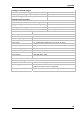
13.2 Pin Layout
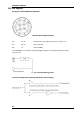
Pin layout of the STG3008-FA Amplifier
Stimulus Out and Electrode IN
Pin 1 to 8 Electrode IN 1 to 8 and Stimulus OUT 1 to 8 (+U / +I)
Pin 9 to 13 Not connected
Pin 14 Ground (GND)
The STG3008-FA can software controlled toggle between recording and stimulation mode
on pins 1 to 8.
Pin 14 connected to ground
Internal switch positions during stimulation and recording