Stimulus Generator 1000 Series Manual
Information in this document is subject to change without notice. No part of this document may be reproduced or transmitted without the express written permission of Multi Channel Systems MCS GmbH. While every precaution has been taken in the preparation of this document, the publisher and the author assume no responsibility for errors or omissions, or for damages resulting from the use of information contained in this document or from the use of programs and source code that may accompany it.
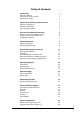
Table of Contents Introduction About this Manual Terms of Use for MC_Stimulus Limitation of Liability 1 1 1 1 Important Information and Instructions Operator's Obligations Guaranty and Liability Important Safety Advice 3 3 3 3 First Use of the Stimulus Generator Welcome to the STG and MC_Stimulus Setting Up and Connecting the STG Installing the Software 5 5 6 7 Operating the STG Operation Overview Operating Multiple STGs 9 9 10 Programming Stimulus Protocols MC_Stimulus Worksheet Pulse Types Autorep
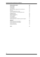
Stimulus Generator 1000 Series User Manual Batch Mode vi 45 Analog Output Signals Output Modes Voltage Mode Current Mode Measuring Output Signals with an Oscilloscope Rise Time Amplitude-Dependant Time Lag Capacitive Behavior of Stimulating Electrodes 49 49 49 54 57 58 61 67 Troubleshooting About Troubleshooting Technical Support Error Messages Strong Peak Artifacts Output Signal Does not Match Programmed Signal 69 69 69 69 71 71 Appendix Technical Specifications STG1001/2 Technical Specifications ST
1 Introduction 1.1 About this Manual This manual comprises all important information about the installation and operation of the stimulus generator STG1000 series and MC_Stimulus software. It is assumed that you have already a basic understanding of technical and software terms. No special skills are required to read this manual.
2 Important Information and Instructions 2.
Stimulus Generator 1000 Series User Manual The product has been built to the state of the art and in accordance with recognized safety engineering rules. The device may only • be used for its intended purpose; • be used when in a perfect condition. • Improper use could lead to serious, even fatal injuries to the user or third parties and damage to the device itself or other material damage. Warning: The device and the software are not intended for medical uses and must not be used on humans.
3 First Use of the Stimulus Generator 3.1 Welcome to the STG and MC_Stimulus Product line overview Stimulus generators of the 1000 and 2000 series are general/purpose stimulators designed to serve a very wide variety of applications, both in vitro and in vivo. Flexible and easy-to-use MC_Stimulus software enables complex stimulus waveforms (both current and voltage).
Stimulus Generator 1000 Series User Manual 3.2 Setting Up and Connecting the STG Provide a power supply and a computer with RS232 serial port in the immediate vicinity of the installation site. Make sure the STG is switched off before you connect it to the power supply. 1. Place the STG on a stable surface, where the air can circulate freely and the STG is not exposed to direct sunlight. 2. Plug the main cable into the socket on the back of the STG. 3. Connect the main cable to the power outlet. 4.
First Use of the Stimulus Generator 3.3 Installing the Software System requirements Software: One of the following Windows© operating systems is required: Windows 2000 or Windows XP (English and German versions supported). Other language versions may lead to software errors. Hardware: RS232 serial port Installing the software Please check the system requirements before you install the software. MCS cannot guarantee that the software works properly if these requirements are not fulfilled.
4 Operating the STG 4.1 Operation Overview Warning: Make sure that you do not come in contact with the cables or the connectors of the STG after you have started the STG. The high voltage and power can lead to injuries. Warning: Do not start the STG if you are unsure about the channel configuration or the nature of the downloaded file. 1. Set up your experiment. 2. Switch the STG on. 3. Set up your stimuli with the MC_Stimulus program. 4. Send the stimulus sequence from an MC_Stimulus file to the STG.
Stimulus Generator 1000 Series User Manual SWEEP Lights green if stimulus file has been downloaded to STG. STG is now ready to use. Lights orange when stimulation is running, that is, output channels are active. 4.2 Operating Multiple STGs If you have more than one STG connected to the same computer, you can choose which STG you like to control from the currently active MC_Stimulus program.
5 Programming Stimulus Protocols 5.1 MC_Stimulus Worksheet You can freely combine any pulse types. Use a separate row for each pulse type. Hint: Several tools are provided for editing whole columns at once or autocreating entries. 1. Select the desired output type first. Click either Voltage or Current under Output Mode on the file window of MC_Stimulus. 2. Click a tab to select an output channel. The according channel worksheet is brought to front. 3. Now you can enter the pulses into the worksheet.
Stimulus Generator 1000 Series User Manual 5.2 Pulse Types Three basic pulse types are available in MC_Stimulus. You can create virtually any pulse by combining different types. • Rectangular • Ramp • Sine wave Note: The time resolution is 20 μs. When you enter time steps that are not a multiple of 20 μs, the length of the step is internally adjusted to a valid value. The changed values do not show up in the worksheet, but invalid values are highlighted in yellow or red.
Programming Stimulus Protocols • Enter each voltage/current level and the duration of the pulse. The voltage/current jumps directly to the specified level. In one row, you can enter up to three voltage/current levels. Use the next row for programming more levels. Ramp pulse type • Define the starting point, end point, and the length of the ramp. The ramp is then build according to these parameters in small single steps of 20 μs.
Stimulus Generator 1000 Series User Manual • 5.3 Define the amplitude and the period of the sine wave. The sine wave is then computed according to these parameters with a minimum resolution of 2 mV and 20 μs. If you enter a negative amplitude, the sine wave starts with its negative alternation. Autorepeating Pulses and Protocols For entering complex stimuli easier and faster, you can repeat rows and groups instead of entering the pulses several times into the worksheet. You can repeat each single row.
Programming Stimulus Protocols 2. Point to the selected cells and right-click to open the context menu. 3. Click Group/Ungroup. The corresponding rows are grouped now. This is indicated by a merging of the Group Repeat cells. 4. Type the number of repeats into the merged Group Repeat cell. Repeating complete pulse protocols (autorepeat function), Continuous Mode 1. 2.
Stimulus Generator 1000 Series User Manual 2. Right-click and click Change Time Unit. 3. Select the desired time unit. All units in the column are set to the selected time unit. Inverting pulses in a column 1. Click any Value column header to select a column. The selected column is highlighted in black.
Programming Stimulus Protocols 2. Right-click and click Invert Selection. The polarity of the signals is switched from positive to negative and vice versa. Incrementing columns This feature is very convenient for setting up long and complex stimuli without entering each value manually. You can enter and edit multiple voltage values or time lengths. You can keep all zero values unchanged with the option Keep Zero.
Stimulus Generator 1000 Series User Manual 2. Right-click and click Increment Selection. 3. Under Type of Increment, select Shift. 4. Enter the desired value. All values in the selected column are modified by the selected factor. In the example, 100 is added to all values, resulting in a total of 100 because the initial value has been 0.
Programming Stimulus Protocols With this option, you enter a base value for modification of all values in the selected column. The first row is modified by the base value. The second row is modified by the double value, the third row by thrice the base value, and so on. With this feature, you can easily set up time or voltage increments. 1. Under Type of Increment, select Count. 2. Enter the desired start value. The value in the first row is incremented by the selected start value of 10.
Stimulus Generator 1000 Series User Manual In the same way, you can set up a stimulus with voltage/current increments. Shifting absolute time or voltage values With this option, the signs of the selected values are ignored. Zeros are never changed, that is, the option Keep Zero cannot be deselected. 1. Under Type of Increment, select Absolute Value. 2. Enter the desired shift factor.
Programming Stimulus Protocols The absolute values of 200 and 200 are both 200. This absolute value of 200 is modified by the shift factor of 50, resulting in 250. The negative value is now 250, and the positive value is 250. (If you had chosen the option Shift instead, the computed result would have been 200 + 50 = 150.) All zero values are not changed. Autocreating entries You can use the Autofill feature to set up advanced time or voltage/current increments.
Stimulus Generator 1000 Series User Manual 5.5 Auto Sync for Autocreating Trigger Pulses If you want to synchronize other devices, for example a MEA1060-BC amplifier or the MC_Card with the stimulus generator, you have to set up the digital output of the Sync Out channels in synchrony to the stimulus pulses. This may sometimes be a bit tricky and time consuming, especially for complex stimulus protocols.
Programming Stimulus Protocols 3. Set the time offset of the TTL's rising edge before the stimulus pulse (Pre Time) and of the TTL's falling edge after the pulse (Post Time). For operating a MEA1060-BC amplifier, a Pre Time of 0 μs and a Post Time of 100 μs are default, but especially the Post Time may have to be adjusted according to your stimulus amplitude and the stimulus artifact suppression performance (please see the user manual of your MEA1060-BC amplifier or the MEA_Select Help for more details). 4.
6 ASCII Import/Export 6.1 Loading Files The ASCII import filter is used to load stimulus protocols from an ASCII file into the stimulus worksheet of MC_Stimulus. You can use this feature for feeding recorded signals (for example, exported from MC_Rack, see the MC_Rack User Manual) into the stimulus generator. The current version of the import filter is version 1.10. Only rectangular waveforms are supported in this version. Fig.
Stimulus Generator 1000 Series User Manual 2. Select an appropriate ASCII file and click Open. The stimuli from the ASCII file are loaded into the active MC_Stimulus worksheet. All previous records are overwritten. Channels that are not present in the ASCII file are empty. You can now edit and download the stimulus file as usual. If the file does not fulfill the requirements of a stimulus file, an error message will show up and tell you in which line the first error occurs.
ASCII Import/Export channels: output mode: format: Make sure you define the total number of channels for the used STG properly (4 channels for an STG with 4 channels, 8 channels for an STG with 8 channels, and so on), according to the software version. You can select the maximum number of channels during the installation of MC_Stimulus. On the Help menu, click About MC_Stimulus to check your current software version.
Stimulus Generator 1000 Series User Manual This is a basic format with two columns of Value and Time each, without Repeat functionality. value time value time Format type 2 With this format, you can repeat rows in the same way as described for the worksheet. Group repeat is not available. value time value time repeat Format type 3 This format type is available only in the current version of the import filter. It allows you to use a third column of Value and Time.
ASCII Import/Export After loading the file into the MC_Stimulus worksheet, you can edit and download the file as usual. Format type 4 This format type is available only in the current version of the import filter. It is the plainest format with only one column for the voltage/current values and one column for the time lengths. This format is the standard format if you want to import data for example from Excel. This format type is generated when exporting MC_Stimulus files as ASCII.
Stimulus Generator 1000 Series User Manual This format type is available only in the current version of the import filter. It allows you to use ramp and sine waveforms as well as rectangular waveforms. You specify the Pulse type in the first column, and the waveform in the three following columns. The general rules for setting up ramp and sine waveforms fully apply (see also Pulse Types). The pulse types are defined by the following numbers: Rectangular = 0, ramp = 1, sine = 2.
ASCII Import/Export After loading the file into the MC_Stimulus worksheet, you can edit and download the file as usual.
Stimulus Generator 1000 Series User Manual 32
7 Stimulus Display 7.1 Selecting Channels To enlarge the display size of the channels, we suggest that you show only those channels you are currently working with. Note: This will affect only the display. It has no effect on the download of signals. To select or deselect channels for downloading, click the Download Channel check boxes in the main window of the program. • Clear the check box of all channels that are not in use. All channels that are not selected are removed from the display. 7.
Stimulus Generator 1000 Series User Manual Scrolling the axes You can scroll the stimuli forward and backward along the time axis, and up and down along the voltage/current axis. 1. Click to enable the scrolling. 2. Click the axis you like to scroll. The mouse pointer becomes a hand. 3. While holding down the mouse button, move the axis to the left and right, or up and down.
Stimulus Display • Click to size the display to fit. The ranges are automatically adjusted to fit the maximum amplitude of each stimulus. The range of the time axis will be set to fit the longest signal.
8 Downloading Stimuli 8.1 Downloading Stimulus Files After having set up the stimulus file, you can download the file to the connected STG. You can select the channels that you want to download or download the complete file. The Sync channel for synchronizing other devices connected to the Sync Out of the STG will always be downloaded, you cannot deselect it. You can start the stimulation directly after the download, or start it manually with the software or hardware controls, or start it on a trigger.
9 General Software Features 9.1 Customizing the Main Window You can customize the size and position of open file windows and the toolbar in MC_Stimulus. • You can hide the toolbar and the status bar by deselecting them on the View menu. • You can arrange the windows with the commands on the Window menu. • Cascade: Use this command to arrange multiple opened windows in an overlapped fashion. The windows are resized to the standard size.
Stimulus Generator 1000 Series User Manual 9.4 Open File Opens a previously saved MC_Stimulus file (*.stm) file Save File Saves the *.
General Software Features 1. On the File menu or on the toolbar, click Open . 2. Browse your folders and choose the desired file. You may only open MC_Stimulus files (*.stm). 3. Click Open. The selected file opens. Save a file 1. On the File menu or on the toolbar, click Save The currently active worksheet is now saved. . You may open the file using MC_Stimulus later on to continue your experiment.
10 Synchronizing Events 10.1 Digital Output Signals (Sync Out) The output of the digital Sync Out output is a 5 V TTL signal. A logic state of 1 means 5 V, and a logic state of 0 means 0 V. Please note that the digital output is about 15 μs faster than the analog output. This small offset is generally sufficient to make sure that the Sync Out signal precedes the stimulation, which is important for synchronizing events.
Stimulus Generator 1000 Series User Manual 10.2 Triggering Stimulation (Trigger In) The external trigger input has to be a TTL signal of at least 20 μs length. TTL pulses shorter than that may not be recognized by the stimulus generator. A TTL pulse is defined as a digital signal for communication between two devices. A voltage between 0 V and 0.8 V is considered as a logical state of 0 (LOW), and a voltage between 2 V and 5 V means a 1 (HIGH).
Synchronizing Events 10.3 Batch Mode You can download and run several stimulus files one after the other in the Batch mode. The first file in the list is downloaded and started directly after the download, or started manually with the software or hardware controls, or started on a trigger. After the first file has been run, the next file in the list is downloaded, and so on, until the last file in the batch list has been run.
Stimulus Generator 1000 Series User Manual Multi Channel Systems MCS MC_Stimulus Batch Control File Version 1.00 c:\Program Files\Multi Channel Systems\MC_Stimulus\BatchExample\Baseline.stm c:\Program Files\Multi Channel Systems\MC_Stimulus\BatchExample\Tetanus.stm c:\Program Files\Multi Channel Systems\MC_Stimulus\BatchExample\TestResponse.stm Operating the STG in Batch mode Important: You can operate the STG in Batch mode only with a valid computer connection.
Synchronizing Events 4. On the Batch menu, click Start to start the download of the first file in the batch list (and the STG if the option Start STG after Batch Download on the Settings menu is selected). The progress of the pulse protocol is displayed in the Status column of the Batch Status Display. 5. Click Stop on the Batch menu to stop the batch if necessary. 6. Close the Batch Status Display with the Close command.
11 Analog Output Signals 11.1 Output Modes The stimulus generator operates in voltage and current mode and has separate voltage and current outputs for each channel. Regardless of the operation mode selected in MC_Stimulus, both current and voltage outputs are active. Please make sure that you use the appropriate output for your experiment. The main difference between the current outputs and the voltage outputs is described in the following.
Stimulus Generator 1000 Series User Manual saving power and suppressing noise. Otherwise, the stimulus generator tries to hold a stable current against the indefinite resistance of the open current output. • The output signals are inverted (multiplied by 1) if you use the U outputs. • If you use the voltage between +U and U, the output signal amplitude is doubled. U represents the ground (replaces GND) in this case. See illustration "Voltage mode: Doubled output signal amplitude".
Analog Output Signals • For amplitudes greater than 200 mV, The time lag between the Sync Out output and the voltage outputs is approximately 12 μs (+/ 2 μs). For more information on the kinetics of smaller amplitudes, please see "Amplitude-Dependant Time Lag".
Stimulus Generator 1000 Series User Manual Fig. 2 Voltage output 1 V and Sync Out. Screen shot from a standard oscilloscope triggered on the Sync Out pulse (see "Measuring output signals with an oscilloscope"). Cyan trace = voltage output (+U), yellow trace = inverted voltage output (U), green trace = TTL output from the Sync Out. Setup suggestions for voltage mode The following illustrations show circuit diagrams of suggested setups.
Analog Output Signals 53
Stimulus Generator 1000 Series User Manual 11.3 Current Mode • If you use current for stimulation, you will usually use the +I and GND outputs. See illustration "Standard setup". • The output signals are inverted (multiplied by 1) if you use the I outputs. • If the load resistance, that is, the electrode impedance is very high, the output voltage can get very high, too. The stimulus generator limits the output voltage to 75 V between +I or I and GND. The guaranteed compliance voltage is 60 V.
Analog Output Signals Fig. 3 Current output 100 μA and Sync Out. Screen shot from a standard oscilloscope triggered on the Sync Out pulse (see "Measuring output signals with an oscilloscope"). Cyan trace = current output (+I), yellow trace = inverted current output (I), green trace = TTL output from the Sync Out. Setup suggestions for current mode The following illustrations show circuit diagrams of suggested setups.
Stimulus Generator 1000 Series User Manual 56
Analog Output Signals 11.4 Measuring Output Signals with an Oscilloscope For test purposes, you can measure the output signals with an oscilloscope. Most standard oscilloscopes have a probe with a ground cable. This probe is usually connected to the oscilloscope via a BNC socket. What you do for measuring the voltage output is the following: You plug in the standard STG cables into the +U output and the corresponding GND output.
Stimulus Generator 1000 Series User Manual 11.5 Rise Time The rise time of the voltage output is constant and independant from the stimulus protocol. The rise time of the current output is no fixed hardware property.The kinetics depend on the amplitude of the current pulse and the load resistance, that is, generally the electrode impedance. The resistance affects the kinetics much stronger than the amplitude. Generally, this does not make much difference for biological applications.
Analog Output Signals Resistance dependency oft rise time The higher the load resistance, the higher the rise time. The rise time (1090%) was measured with increasing load resistances and a constant current amplitude of 100 μA. For 100 μA pulses, the relationship is linear up to the maximum load resistance (please see "Current Mode") as shown by the following (Boltzmann fitted) curve.
Stimulus Generator 1000 Series User Manual Fig. 4 Rise time with programmed 500 mV and 50 μA pulses, 10 kΩ load resistance. The rise time is about 4 μs for the 500 mV voltage pulse (yellow), and < 1 μs for the 50 μA current pulse (cyan). Fig. 5 Rise time with programmed 5 V and 500 μA pulses, 10 kΩ load resistance. The kinetics and the rise time of the 5 V voltage pulse (yellow) are comparable to the 500 mV pulse. The approx.
Analog Output Signals Fig. 6 Rise time with programmed 5 V and 500 μA pulses, 100 kΩ load resistance. With a higher load resistance, the current pulse (cyan) shows a different kinetic behavior: There is no overshoot, and the rise time increases significantly (about 20 μs). 11.6 Amplitude-Dependant Time Lag For most standard applications, you can assume that the STG output is identical (in normal tolerances of electronic components) to the stimulus protocol in the WYSIWYG editor of the MC_Stimulus program.
Stimulus Generator 1000 Series User Manual The time lag of the positive phase (for the +U and +I outputs, negative phase for U and I) is higher than that of the negative phase. If the polarity switches directly from negative to positive, you will observe a time lag of a few microseconds at 0 V in-between the phases. For pulses with positive phase (for the +U and +I outputs, negative phase for U and I), the time lag of the falling edge is negligible in contrast to the time lag of the rising edge.
Analog Output Signals Fig. 8 STG output with programmed biphasic 50 mV pulses, negative phase first, duration 100 μs for each phase. This figure shows the output of the same programmed pulse, but with inverted polarities. Regardless whether the positive or the negative phase comes first, always the positive phase of the +U output shows a higher time lag and is shorter than the negative phase. If the polarities are switched directly from negative to positive, there is a time lag at 0 mV between the phases.
Stimulus Generator 1000 Series User Manual Fig. 9 STG output with programmed biphasic 50 mV and 5 μA pulses, duration 100 μs for each phase. The negative phase of the inverted voltage output (U, yellow) and the positive phase of the current output (+I, cyan) are more delayed and significantly shorter than the other phases.
Analog Output Signals Fig. 10 STG output with programmed biphasic 100 mV and 10 μA pulses, duration 100 μs for each phase. In comparison to the 50 mV pulses, the time lag of the negative phase of the U output (yellow) is much smaller (less than 10 μs), and the actual current output amplitudes (cyan) match the setpoint current.
Stimulus Generator 1000 Series User Manual Fig. 11 STG output with programmed biphasic 200 mV and 20 μA pulses, duration 100 μs for each phase. With a voltage amplitude of 200 mV (U, yellow), there is almost no delay between the positive and negative phase. The top part of the figure shows all three voltage steps (50 mV, 100 mV, and 200 mV). You can clearly see that the delay between the phases decreases significantly with increasing pulse amplitude.
Analog Output Signals Fig. 12 STG output with programmed 200 mV and 20 μA pulses, duration 100 μs for each phase. About 10 μs is the standard delay of the voltage output at 200 mV (U, yellow). The delay of the current output at 20 μA (cyan) is increased due to the small current amplitude. At 100 μA or higher, the time lag of the current output would be comparable to the standard delay of the voltage output. 11.
Stimulus Generator 1000 Series User Manual The following illustration shows the effect of a biphasic current pulse on the discharge of the stimulating electrode. As you can see, the first monophasic pulse is followed immediately by a pulse of the opposite polarity and the same product of current and time.
12 Troubleshooting 12.1 About Troubleshooting Most problems occur seldom and only under specific circumstances. In most cases, it is only a minor problem that can be easily avoided or solved. If the problem persists, please contact your local retailer. The highly qualified staff will be glad to help you. Please inform your local retailer as well, if other problems that are not mentioned in this documentation occur, even if you have solved the problem on your own.
Stimulus Generator 1000 Series User Manual The worksheet is empty. No data is present that can be downloaded. Please create a stimulus or open a stimulus file before downloading. There is no stimulus generator connected to the computer or the STG may be switched off. Please check the computer connection and the status lamp of the STG. There is no valid connection to an STG. Download of data is not possible. Please check the computer connection and the status lamp of the STG.
Troubleshooting Each data column must have a header (value, time, or repeat). The number of data columns has to be consistent for all lines in a given ASCII file (for example, value, time, value, time). This error message indicates that there is a current/voltage value or a time point missing in line 12. The ASCII file contains current/voltage values outside the STG's range. For example, if the STG's output range is +8000 mV, all values above +8000 mV are set to +8000 mV. 12.
Stimulus Generator 1000 Series User Manual You operate the STG in current mode, and the electrode resistance of the stimulating electrodes is too high. According to Ohm's law, the electrode resistance directly affects the kinetics of the current output. The rise time increases with an increasing electrode resistance. If the electrode resistance is too high for the compliance voltage, the output signal will be clipped. • Try to stimulate in voltage mode.
13 Appendix 13.1 Technical Specifications STG1001/2 Operating temperature Storage temperature 10 °C to 35 °C 0 °C to 50 °C Dimensions (W x D x H) 170 mm x 240 mm x 60 mm Weight 1.2 kg Fuse 1 A @ 100 to 230 V, slow blow Supply voltage (external power supply) 100240 VAC @ 47 to 63 Hz Number of analog output channels 1 (STG1001) or 2 (STG1002) Output voltage 8 V to + 8V @ max.
Stimulus Generator 1000 Series User Manual Operating system Windows© 98, ME, NT, 2000, or XP; English and German versions supported Data import ASCII file format 13.2 Technical Specifications STG1004/8 Operating temperature Storage temperature 10 °C to 35 °C 0 °C to 50 °C Dimensions (W x D x H) 275 mm x 330 mm x 115 mm Weight 4.8 kg Fuse 0.2 A @ 230 V, slow blow; 0.
Appendix MC_Stimulus program Operating system Windows© 98, ME, NT, 2000, or XP; English and German versions supported Data import ASCII file format 13.3 Contact Information Local retailer Please see the list of official MCS distributors on the MCS web site. User forum The Multi Channel Systems User Forum provides the opportunity for you to exchange your experience or thoughts with other users worldwide.
Stimulus Generator 1000 Series User Manual Red single pole cable CR-BC Black single pole cable CB-BC Blue single pole cable CBL-BC Red single pole cable CR Black single pole cable CB For connecting the STG to the MEA1060-Inv/Up-BC amplifier with blanking circuit For connecting the STG to the standard MEA1060-Inv/Up amplifier MEA amplifiers Product Product Number Description MEA amplifier for inverted microscopes MEA1060-Inv Probe interface and 60 channel pre- and filter amplifier with custo
14 Index 77
Stimulus Generator 1000 Series User Manual 78
Compiler warnings A About dialog 39 Amplifier blanking.............................................43 connecting...................................49, 54 Amplitude effects on kinetics .............................61 effects on rise time ...........................58 of sine wave ......................................11 Analog current output...................................54 input ....................................................6 voltage output ..................................
Stimulus Generator 1000 Series User Manual menu..................................................39 Electrode capacitive behavior ...........................68 Inverting pulses................................................. 15 selection ............................................ 15 End point of ramp ....................................11 run........................................................9 K Error Messages L 71 Keep Zero 15 F Length of pulse.............................................
Index 33 Period of sine wave ......................................11 Scrolling Port digital...................................................6 serial.....................................................6 USB .......................................................6 Settings Auto Sync .......................................... 23 menu ................................................. 39 Port Settings change .................................................9 multiple STGs................................
Stimulus Generator 1000 Series User Manual connectors ...........................................6 digital TTL outputs............................43 System requirements 7 T Tile 39 Time change time units .............................15 resolution ..........................................11 rise time .............................................58 time lag and accuracy.......................61 time offset for Auto Sync .................23 Timing accuracy of pulses .............................
83