STG-Lite Manual
Information in this document is subject to change without notice. No part of this document may be reproduced or transmitted without the express written permission of Multi Channel Systems MCS GmbH. While every precaution has been taken in the preparation of this document, the publisher and the author assume no responsibility for errors or omissions, or for damages resulting from the use of information contained in this document or from the use of programs and source code that may accompany it.
Table of Contents Introduction Introduction 1 1 Important Safety Advices Guarantee and Liability Operator's Obligations Important Safety Advice Terms of Use 3 3 3 3 3 Installation System Requirements Installing STG-Lite Setting Up and Connecting the STG 5 5 5 6 Use of STG-Lite Welcome to STG-Lite Stimulation Pattern: Waves Stimulation Pattern: Pulse 9 9 13 15 Troubleshooting Error Messages Technical Support 19 19 19 Index 21 iii
1 Introduction 1.1 Introduction The software STG-Lite is supposed to be an alternative to the default program MC_Stimulus II for the control of the basic features of the Multi Channel Systems stimulus generators. The software controls up to four channels of the STG stimulus generators of the 2000, 3000 and 4000 series. STG-Lite requires an USB connection between computer and stimulus generator. Therefore, it can not be used to control the stimulus generators STG1002, 1004 and 1008.
2 Important Safety Advices 2.1 Guarantee and Liability The General conditions of sale and delivery of Multi Channel Systems MCS GmbH always apply. The operator will receive these no later than on conclusion of the contract. Multi Channel Systems MCS GmbH makes no guarantee as to the accuracy of any and all tests and data generated by the use of the device or the software. It is up to the user to use good laboratory practice to establish the validity of his findings.
STG-Lite Manual 2.4 Important Safety Advice Warning: Make sure to read the following advice prior to install or to use the device and the software. If you do not fulfill all requirements stated below, this may lead to malfunctions or breakage of connected hardware, or even fatal injuries. Warning: Obey always the rules of local regulations and laws. Only qualified personnel should be allowed to perform laboratory work.
3 Installation 3.1 System Requirements System requirements Software: One of the following Microsoft Windows ® operating systems is required: Windows 7, XP, or Vista (English and German versions supported) with the NT file system. Other language versions may lead to software errors. Recommended Software: MC_Rack Data Acquisition and Analysis Software. Hardware: STG 2000, 3000, 4000 series.
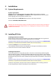
STG-Lite Manual 3.3 Setting Up and Connecting the STG Note: You can use a USB hub for connecting the STG to the computer, for example, if you have no free USB port or if you need to extend the USB cable. Provide a power supply and a computer with USB port in the immediate vicinity of the installation site. Make sure the STG is switched off before you connect it to the power supply. 1. Place the STG on a stable surface, where the air can circulate freely and the STG is not exposed to direct sunlight. 2.
Installation Illustration of the STG 2000 series rear panel and connectors Rear panel of the upgraded STG version (from 1000 series to 2000) 7
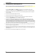
STG-Lite Manual Illustration of the STG 4000 series rear panel and connectors 8
4 Use of STG-Lite 4.1 Welcome to STG-Lite The STG-Lite software program connects to the stimulus generator via USB (2.0 High Speed) cable. Changes made in the software are downloaded immediately, without the need for an additional user command. There is an automatic TTL signal on the Sync Out 1 of the stimulus generator together with each stimulation pulse. You can control voltage driven stimulation only. The STG-Lite program has two main menus for two stimulation modes "wave" or "pulses".
STG-Lite Manual STG: Serial number. Drop down list of connected STG devices if more than one stimulus generator are connected. Please choose the actual used stimulus generator. Number of channels: Select radio button 1, if you want to stimulate on one channel, select 2, if you want to stimulate on two channels, select 4 to stimulate on four channels. Selecting two channels, the main menu will be doubled for independent settings on both channels. The display changes accordingly.
Use of STG-Lite Stimulation patterns: You can choose weather you want to stimulate via waves or via pulses. The main menu changes accordingly.
STG-Lite Manual Info: The dialog shows basic information about the STG-Lite software and about the connected stimulus generator STG.
Use of STG-Lite 4.2 Stimulation Pattern: Waves Select stimulation pattern "Wave". The main menu with default settings appears. Channel 1 The option "Start" for channel 1 appears when no waves are downloaded. The option "Stop" for channel 1 appears when program is running. The currently selected values for frequency (Hz) and amplitude (mV) are displayed below the "Start / Stop" button. Signal The signal can be delivered as rectangular waves, ramps or sine waves.
STG-Lite Manual Frequency The waves can be delivered in a frequency between 0.1 and 10000 Hz. Click 1, 10, 100 or 1000 Hz as a basic value. Fine tune the frequency between 0.1 and 10 times the basic value with the virtual control dial. Click onto the red point of the control dial and move it while keeping the left mouse button pressed. The exact value of the frequency will be displayed below the "Start / Stop" button. You can change the value while program is running.
Use of STG-Lite 4.3 Stimulation Pattern: Pulse Select stimulation pattern "Pulses". The main menu with default settings appears. Channel 1 The option "Start" for channel 1 appears when no pulses are downloaded. The option "Stop" for channel 1 appears when program is running. When using the option "Train" under "Pulse Pattern", the remaining time of the pulse train (in seconds) is displayed below the "Start / Stop" button.
STG-Lite Manual Amplitude Select the amplitude of the pulse. The unit is millivolt (mV). Click onto the red point of the control dial and move it while keeping the left mouse button pressed. The exact value of the amplitude will be displayed below the control dial. Pulse Pattern: Single or paired pulses Select the stimulus pulse pattern: "Single". You can select single or paired pulse. If you select "single pulse", you have to define the frequency (Hz) for the single pulses from the drop down menu.
Use of STG-Lite A classic theta burst consists of four pulses at 100 Hz, repeated ten times with intervals of 200 ms, for example. Digital Sync Out: Synchronization of stimulation and recording A TTL pulse is defined as a digital signal for communication between two devices. A voltage between 0 V and 0.8 V is considered as a logical state of 0 (LOW), and a voltage between 2 V and 5 V means a logical state of 1 (HIGH).
5 Troubleshooting 5.1 Error Messages Firmware Update STG-Lite needs a firmware update. If you do not have the adapted firmware an error message will appear. Please contact support@multichannelsystems.com. 5.2 Technical Support If you have any questions or if any problem occurs that is not mentioned in this help document, please contact your local retailer. A list of local retailers for MCS products can be found on the MCS web site. The highly qualified staff will be glad to help you. http://www.
6 Index 21
STG-Lite Manual A Amplitude 14 Amplitude and DC Offset 12 E Error message 17 Firmware update...............................17 F Frequency 12 I Information 9 M Main Menu 9 pulse.....................................................9 wave.....................................................9 MC_Stimulus II 9 N Number of channels 14 P Pulse 14 inter pulse interval............................14 paired pulse.......................................14 pulse pattern .....................................
23