Roboocyte2 Scripting
Table of Contents 1 1.1 1.2 1.3 2 2.1 2.2 2.3 3 3.1 3.2 3.3 4 4.1 4.2 Introduction Java Script 1.1.1 Roboocyte2 Specific Features 1.1.2 Oocyte Loop Variables 1.2.1 JavaScript Variables 1.2.2 User Defined Interactive Variables 1.2.3 Predefined Variables 1.2.4 Read-only Variables Complete List of Commands 1.3.1 Conditions 1.3.2 Robo2. GUI-Commands 1.3.3 Robo2. Variable Handling Commands 1.3.4 Robo2. Movement Commands 1.3.5 Robo2. Amplifier and Data Acquisition Commands 1.3.6 Robo2.
Roboocyte2 Manual 4.3 Transfer Port Valve Commands 4.4 Examples 4.4.1 Differences between Roboflow and Gilson 4.4.2 Solution Exchange - Roboflow vs. Gilson 4.4.
1 Introduction 1.1 Java Script Roboocyte2 scripts are written in a JavaScript like language. The syntax (control structures, variables, functions, arrays) is conforming to JavaScript, other JavaScript functionality, particularly the document (and other HTML specific things like DOM handling, libraries etc.) is NOT supported. 1.1.1 Roboocyte2 Specific Features The Roboocyte2 is controlled via 4 JavaScript objects: 1. Robo2 (the robot hardware) 2. RecDisplay (display of the recordings) 3.
Roboocyte2 Manual 1.2.2 User Defined Interactive Variables There are also user defined interactively changeable variables. These variable are defined by the command SetDialogVariable. Robo2.SetDialogVariable("clampvoltage", -60, "Recording Voltage in mV"); generates the variable "clampvoltage" with the value -60. The comment "Recording Voltage in mV" will help you to identify the meaning of the variable when opening the dialog.
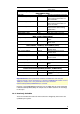
offset check Robo2.Impale(MIN_RMP, IMPALEMENT_STEPS, IMPALEMENT_STEP, IMPALEMENT_WAIT) MIN_RMP -15 mV minimum membrane potential IMPALEMENT_STEPS_I 6 number of z axis steps to move down during impalement of the I electrode IMPALEMENT_STEPS_U 2 number of z axis steps to move down during impalement of the U electrode IMPALEMENT_STEPS 8 maximum number of z axis steps to move down during impalement IMPALEMENT_STEP 50 µm step size of impalement step IMPALEMENT_WAIT 2 sec wait after each z axis step Robo2.
Roboocyte2 Manual Variable Robo2.
1.3 Complete List of Commands 1.3.
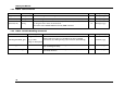
Roboocyte2 Manual 1.3.2 Robo2. GUI-Commands Robo2. Parameter(s) Action Log("x") string Plots the message "x" in the Log window --- Messages_eg.js Information("x") string Opens a dialog with "x". Script execution is suspended until OK is pressed R- Messages_eg.js string Opens a dialog with "x". Different control paths in the script can be executed by using the return value of the function. R- Messages_eg.js Question("x") Cond.
1.3.4 Robo2. Movement Commands Robo2. Parameter(s) Action Cond. Example Script MoveToWell(x) int: well number moves carrier to given well x, with x from 0 to 95 R- Movement_eg.js MoveToHomePos() --- moves Z-axis and carrier to Home-Position R- Movement_eg.js MoveToParkPos() --- moves Z-axis and carrier to Park-Position R- Movement_eg.js MoveToChangePlatePos() --- moves Z-axis up and carrier to a position to change the plate R- Movement_eg.
Roboocyte2 Manual 1.3.5 Robo2. Amplifier and Data Acquisition Commands Robo2. Parameter(s) Action SetHoldingVoltage(x) int: voltage in mV SetVoltageClamp() SetHoldingCurrent(x) SetCurrentClamp() SetAmplifierCoefficients(x, y) SetSampleRate(x) --int: current in nA --int: x = proportional gain int: y = integral gain int: samplerate Cond. Example Script sets clamp voltage to x mV --- Acquisition_eg.js sets amplifier to voltage clamp mode --- Acquisition_eg.
1.3.6 Robo2. Data Analysis Commands Robo2. SetBaselineROI(x,y) SetBaselineROIMilliSec(x,y) SetDriftCorrectionROI(x,y) SetDriftCorrectionROIMilliSec(x,y) SetAnalysisROI(x,y) SetAnalysisROIMilliSec(x,y) Parameter(s) Action int: x = left in s sets the region of interest (ROI) used for the baseline calculation. --- Data_eg.js sets the region of interest (ROI) used for the baseline calculation. --- --- sets the left and right cursor positions used to calculate the drift correction. --- Data_eg.
Roboocyte2 Manual 1.3.7 Robo2. Database Commands Robo2. TransmitRecording(x) Parameter(s) Action REC_TAG_VOLTAGE, REC_TAG_COMPOUND, Writes recording tag to database. REC_TAG_REF_VOLTAGE, REC_TAG_REF_COMPOUND REC_TAG_REF_COMPOUND: not used for generating DR curves Cond. Example Script R+ valves_tags_eg.
1.3.8 Robo2. Timing Commands Robo2. Parameter(s) Action Wait(x) int: time waits for x seconds before executing the next command --- WaitMilliSec(x) int: time waits for x milliseconds before executing the next command --- starts timer, see also variables TIME and TIME_S --- waits until x seconds from timer start have been passed. --- StartTimer() WaitForTimer(x) 1.3.9 --int: time Cond. Example Script Robo2. Liquid Handling (Roboflow) Commands Robo2.
Roboocyte2 Manual 1.3.10 Robo2. High Level Commands Robo2. Parameter(s) Action ResistanceCheck_I(a,b) a = MIN_RESISTANCE_I b = MAX_RESISTANCE_I R: bool Cond.
1.3.11 RecDisplay. Recording Display Commands RecDisplay. Parameter(s) Clear() --- Action Cond. Example Script clears the recording display --- valves_tags_eg.js SetMode(x) x = DISP_SINGLE or DISP_OVERLAY sets recording display to overlay or single trace mode --- --- SetXAxis(x,y) int: min int: max sets x-axis range from min to max in seconds --- valves_tags_eg.
Roboocyte2 Manual 1.3.13 Gilson. Gilson Commands Gilson. Parameter(s) MoveToTube(x,y) int: x = slot int: y= tube Action Cond. moves to tube in slot 1 ..
Appendix 2 Example Script "Dose-Response" In the following chapter, you will learn how a typical recording script is built. As an example we will use the script: "dose-response.js" which can be found on the Roboocyte Setup CD. Another example script which can be found on the Roboocyte CD is the script "standard_procedures.js".
Roboocyte2 Manual 2.1.2 Working with Pre-defined Variables Pre-defined variables are already existing variables with predefined default variable names and values (see table in chapter 1.2.3).
Appendix The command "Robo2.ShowStandardDialog();" opens a window after starting the script listing all predefined variables. All values can be changed here, but again changes are not permanent and only valid for a single script execution. If you want to change values "permanently" you have to change them in the script text. The next section in the script - Initialization - uses some of the predefined variables. After defining variables and their respective values, the "oocyte loop" can be initiated. 2.
Roboocyte2 Manual The oocyte loop itself has only 4 lines (lines 89, 90, 91 and 105 in the example shown above), but, before terminating the oocyte loop by the final curly bracket, do not forget to stop the valve pump to avoid flooding (lines 101, 102 and 103) 2.3 Standard Routines executed before Recording Protocol Before starting the recording of data, a number of steps and routines have to be started which usually will not change for different kind of recording protocols. 2.3.
Appendix 2.3.2 Switching to Current Clamp Mode After moving the electrodes into liquid, the amplifier is set to Current Clamp Mode. Robo2.SetHoldingCurrent(0); sets holding current to 0 nA Robo2.SetCurrentClamp(); sets the amplifier to current clamp mode Before starting control recording, scaling of the Control Display axes is performed. Units are seconds, mV and nA, respectively. 2.3.
Roboocyte2 Manual If the electrode resistances are within the range (between MIN_RESISTANCE and MAX_RESISTANCE) the script proceeds; if not (else), the script breaks and continues with the next oocyte. Now, after completing electrode offset compensation, oocyte impalement can be started. 2.3.5 Oocyte Impalement The oocyte impalement is performed by using the command: Robo2.
Appendix If the impalement was not successful, i.e. if the membrane potential U = MIN_RMP was not reached after n = IMPALEMENT_STEPS steps with the step distance d = IMPALEMENT_STEP the run is continued with the next oocyte. Before moving to the next oocyte pumps and valves should be closed (lines 170 - 172). IMPALEMENT_WAIT is the waiting time between individual steps of the z-axis in seconds. If impalement was successful, the script continues after line 175.
Roboocyte2 Manual where MIN_INITIAL_LEAKCURRENT and MAX_INITIAL_LEAKCURRENT are predefined variables with default values -10000 and +200, respectively. If the leak current is within the range the script continues after line 209; if not, the run continues with the next selected oocyte. Again, commands for stopping pumps and valves should be included (lines 205 - 207). 2.3.8 Final Leak Current Test with Perfusion After the successful initial leak current check, i.e.
Appendix 3 Recording Protocol Examples 3.1 Using the Dose-Response Script as a Template The example script "dose-response.js" is a typical dose-response recording protocol which can be used as a template for all kind of dose-response like protocols. The recording protocol specific part is located between line 254 and 365. The part of the script outside of "Protocol specific part starts here/ Protocol specific part stops here" comment can be used as a starting-point for your own scripts. 3.
Roboocyte2 Manual Robo2.SetBaselineROI(pre_agonist_s - 3, pre_agonist_s - 1); Robo2.SetAnalysisROI(pre_agonist_s, pre_agonist_s + agonist_s); ControlDisplay.SetXAxis(0, pre_agonist_s + agonist_s + recorded_washout_s) ControlDisplay.SetYAxis_I(-10000, 100) Above JavaScript commands lead to durations listed in the following table.
Appendix the response can be compared to the values assigned to the user-defined variables minResponse and maxResponse the result of which determines whether the script continues at line 297 or is stopped and continued with the oocyte from the next well.
Roboocyte2 Manual The loop variable is the valve number, starting with the user defined variable first_compound and ending with last_compound. If needed, a leak test can be placed before the application of every agonist application. If the leak test fails, the message "leak current is not in range - next oocyte" is send to the log window, all pumps and valves are switched off and the protocol continues with the next selected oocyte.
Appendix The analysis ROI covers the whole duration of the voltage (test) pulse except the first 10 ms in order to avoid interference with the capacitive transient caused by the voltage jump. Next, the recording is started. The sequence generates the following voltage jump: a. Start the recording b. 100 ms at -60 mV c. 200 ms at +50 mV d. 200 ms at -60 mV e.
Roboocyte2 Manual Although voltage step protocols can be defined line by line with the script language, voltage protocols should be generated by the built-in graphical user interface (GUI). Please refer to the Roboocyte2 manual for details.
Appendix 4 Using the Gilson Liquid Handler Commands controlling the Gilson liquid handler can be separated in movement commands, commands controlling the peristaltic pump connected to the Gilson liquid handler, and commands controlling the magnetic valves of the Gilson's transfer ports. If you are using the liquid handler, scripts have to be modified, using Gilson commands instead of Roboflow commands.
Roboocyte2 Manual The transfer ports offer you the option to work with larger solution volumes, e.g. for often used buffers or compounds. Using the transfer ports would mean moving the needle to the transfer port with the respective movement commands, opening the respective valves with the commands listed above, and finally switching the Minipulse pump on to aspirate solution from the transfer port. 4.
Appendix Gilson.PumpBackward(2600); Robo2.WaitMilliSec(600); Gilson.PumpStop(); Robo2.OpenValve(1); Gilson.MoveToTube(1, 1); Gilson.PumpBackward(2600); Robo2.Wait(10); Robo2.Wait(10); Same sequence from above listed sequentially. Roboflow Gilson Robo2.OpenValve(1); Gilson.MoveToTube(1, 1); Robo2.ValvePumpOn(5000); Gilson.PumpBackward(2600); Robo2.Wait(5); Robo2.Wait(10); Robo2.Wait(5); Gilson.PumpStop(); Gilson.MoveUp(); Robo2.OpenValve(1); Gilson.PumpBackward(2600); Robo2.Wait(10); Robo2.
Roboocyte2 Manual Roboflow Gilson -->Robo2.OpenValve(1); -->Gilson.MoveToTube(1, 1); -->Robo2.ValvePumpOn(5000); -->Gilson.PumpBackward(2600); Robo2.SetBaselineROI(2,5); Robo2.SetBaselineROI(2+delay, 4+delay); Robo2.SetAnalysisROI(5, 15); Robo2.SetAnalysisROI(5+delay, 15+delay); Robo2.StartRecording(); Robo2.StartRecording(); Robo2.TransmitRecording(REC_TAG_COMPO UND); Robo2.TransmitRecording(REC_TAG_COMPOU ND); Robo2.TransmitCompoundValve( 2); Robo2.TransmitCompoundGilson(1, 2); Robo2.