Roboocyte2 Manual
Information in this document is subject to change without notice. No part of this document may be reproduced or transmitted without the express written permission of Multi Channel Systems MCS GmbH. While every precaution has been taken in the preparation of this document, the publisher and the author assume no responsibility for errors or omissions, or for damages resulting from the use of information contained in this document or from the use of programs and source code that may accompany it.
Table of Contents Introduction About this Manual Welcome to the Roboocyte2 1 1 2 Important Safety Advices Important Safety Advice High Voltage Requirements for the Installation Compressed Air Supply Handling of the Carrier Handling of the Z-Axes Handling of the Ready to Use TEVC Probes Regular Backups Guarantee and Liability Operator's Obligations 7 7 7 7 8 8 8 8 9 9 9 Setting Up Hardware and Software Setting up Roboocyte2 Hardware and Software Setting up the Roboflow-System Setting Up the Gilson GX-271
Roboocyte2 Manual Recording with Roboocyte2 Control Software Preparations for Recording Alignment Testing the Electrode Resistance Liquid Handling Recording Data Manual Recording Step by Step Automated Recording Step by Step Writing a Script with the built-in Script Editor iv 69 69 72 74 75 77 77 81 82 Analysis with Roboocyte2+ The Roboocyte2+ Analysis Software Analysis with Roboocyte2+ Selecting a Database and Loading a Plate File Analyzer Displays Data Export to ASCII Format 85 85 85 88 90 107 Appen
1 Introduction 1.1 About this Manual This manual comprises all important information about the first installation of the Roboocyte2 hardware and software and about the daily work with the Roboocyte2. It is assumed that you already have a basic understanding of technical and software terms. Thus, no special skills are required to read this manual. If you need information on the Roboocyte2 Scripting Language, please refer to the Roboocyte2 Scripting Language manual.
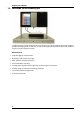
Roboocyte2 Manual 1.2 Welcome to the Roboocyte2 The Roboocyte2 is a fully-automated all-in-one solution for high-throughput screenings of ligandgated and voltage-gated ion channels, as well as electrogenic transporters based on the standard Xenopus oocytes expression system. Main Features High throughput of experiments. Recording of 96 oocytes over night. 24 h operation without supervision. Automated TEVC recording.
Introduction Operation Summary The integrated TEVC amplifier operates in voltage and current clamp mode. Instead of having a vast amount of different pull down menus, there is one clearly structured menu bar and also a toolbar presenting commonly used commands. Therefore, you will quickly become familiar with the Roboocyte2. The first step is to set up your "virtual" well plate according to your "real" well plate and the experiment.
Roboocyte2 Manual The integrated pinch valve Roboflow-System is an ideal perfusion system for drug receptor characterizations and quick expression tests. The Roboflow is computer controlled and works virtually pulsation-free, thus minimizing noise during recording. For high-throughput screens, the Roboocyte2 uses the advantages of an industry-standard liquid handler from Gilson (optional). The Gilson liquid handler version GX-271 is supported.
Introduction The Roboocyte2 Software Operate the Roboocyte2, collect and evaluate the data by using the Roboocyte2 software. The easy-to-use graphical user interface of the Roboocyte2 software makes daily work with the Roboocyte2 quick and easy. Recording is started by a single mouse click. The Roboocyte2 controls the run for all 96 oocytes automatically, even including a wash cycle. Thus the recording can go on overnight, unsupervised.
2 Important Safety Advices 2.1 Important Safety Advice Warning: Make sure to read the following advice prior to installations of the Roboocyte2. If you do not fulfill all requirements stated below, this may lead to malfunctions, breakage, or even fatal injuries. Obey always the rules of local regulations and laws. Only qualified personnel should be allowed to perform laboratory work. Work according to good laboratory practice to obtain best results and to minimize risks.
Roboocyte2 Manual 2.1.3 Compressed Air Supply Even small amounts of water in the compressed air can lead to a corrosion of the carrier. Other contaminations can also result in malfunctions. Use only compressed air fulfilling the following standards. The air must be absolutely free of water, oil, and any particles. When air is compressed, the humidity in the air is concentrated into a smaller area, frequently condensing inside the air hoses. Use a water separator to remove water from the air.
Important Safety Advices 2.1.7 Regular Backups You (or the administrator) should perform backups of the Roboocyte2 data files (*.rcd files) and of the Microsoft Access database (*.accdb) at regular intervals and to appropriate media for preventing data loss. Data loss may be caused by power failure, system and software errors. INI file Modifications If you remove or edit text of an INI file, the software may cause severe problems. Some INI files relate to hardware functions.
3 Setting Up Hardware and Software 3.1 Setting up Roboocyte2 Hardware and Software Connect all cables as described below. Warning: Carefully lay and secure the cords. Remember that someone could easily trip over a loose cable. Note: All electrical connections are clearly marked and the plug coding prevents confusion.
Roboocyte2 Manual Connecting the Carrier 1. Plug the carrier connector into the according socket located on the Roboocyte2's rear panel. 2. Connect the Compressed Air Outlet to the carrier. Warning: Confusion of the compressed air's inlet and outlet may destroy the device. Have a close look at the preceding picture of the Roboocyte2's rear panel and take care to connect the lines properly. Connecting the Roboflow 1. Plug the female connector into the male socket of the Roboflow. 2.
Setting Up Hardware and Software 3.2 Setting up the Roboflow-System The Roboflow-System has been especially designed to work with Roboocyte2. The system consists of two peristaltic pumps and twelve pinch valves. The valve pump for the compounds on the movable slide of the Roboflow manages the fluidic inflow; the waste pump installed on the right side of the front panel is for aspiration of the fluids from the wells.
Roboocyte2 Manual Attaching the Manifold Please control the provided manifold, specially the connections of the provided tubes to the manifold. If you are going to use only some of the twelve tubes, please connect the useless tubes to Ringer solution, for example, but do not leave the manifold connections open. The manifold is fixed via magnetic forces to the housing of the slide of the Roboflow. Adjust the manifold in a deviation of about 15 degrees to minimize the distance to the tube connection.
Setting Up Hardware and Software Attaching the Tubing to the Valve Pump Open the screw of the press bracket of the valve pump and remove the press bracket. Insert the tube section (PPRT1.14) provided for the valve pump. Remount the press bracket and close the screw carefully. Please start the valve pump by software control to move the tube section into the pump housing, until the spacer stops this process.
Roboocyte2 Manual Software Control for Inserting the Tube Section (PPRT1.14( in the Valve Pump Please switch to the "Manual Mode" in Roboocyte2 control software. Click the icon or select main menu "Tools" "Manual Mode". Open the "Liquid Handling" tab page. Press the button "Valve Pump" to run the pump as long as it needs to insert the tube section into the pump housing, until the spacer stops this process. Stop the pump by clicking the button again.
Setting Up Hardware and Software Attaching the Tubing of the Waste Pump Connect the tubing to the provided connectors of the waste pump (PPRT2.29). The silicone tube (ID 1.0 mm, OD 2.4 mm, length 540 mm) coming from the left side of the aspiration pump is directly connected to the outlet of the measuring head of the Roboocyte2. Please guide this tube also through the plastic tube holder to ensure the correct attachment. The PVC tube (ID 2.0 mm, OD 4.
Roboocyte2 Manual 3.3 Setting Up the Gilson GX-271 Liquid Handler For high-throughput screens, the Roboocyte2 can be used with an industry standard liquid handler from Gilson (optional), the GX-271. Warning: Only hardware configurations and probes provided by Multi Channel Systems GmbH are supported. Other versions may lead to incompatibilities, up to damages to the hardware (needle breakage for example).
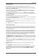
Setting Up Hardware and Software General Setup of the GX-271 Liquid Handler 1. Unpack and set up the Minipuls peristaltic pump (MP3) and the Gilson GX-271 liquid handler according to the descriptions in the Minipuls 3 Peristaltic Pump User’s Guide and the GX-271 Liquid Handlers User's Guide from Gilson in the immediate vicinity of the Roboocyte2 (preferably on the right side, next to the recording z-arm).
Roboocyte2 Manual 1. Set the z-arm to the height of 175 mm by using the ruler integrated into the z-arm, marked by a blue arrow in the preceding illustration. 2. Insert the stop pin into the hole labeled S2, marked by a blue arrow in the preceding illustration. Installing the Probe and Transfer Tubing 1. Install the provided needle to the GX-271 as described in the chapter "Probe Installation" of the GX-271 Liquid Handlers User's Guide from Gilson. 2.
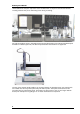
Setting Up Hardware and Software Electrical Connections Please note that the Roboocyte2 needs to be connected to the Gilson GX-271 via the Gilson 508 Interface Module. 1. Connect the Gilson z-arm to the z-arm port of the GX-271. 2. Connect the two solenoid valves of the transfer port station to the solenoid valve ports. Make sure that the cable labeled 1 is connected to the left, and the cable 2 connected to the right port, as shown in the preceding illustration. 3.
Roboocyte2 Manual Enabling the Gilson Liquid Handler GX-271 in the Roboocyte2 Program After installing the Roboocyte2 program, enable liquid handler in the main menu "Settings", "Options" dialog box. After changing the settings in the check box, please close the Roboocyte2 software and start the program again to activate the communication with the Gilson.
Setting Up Hardware and Software 3.4 Installing the Software Roboocyte2 The operating system Microsoft Windows ® 7 (32 and 64 bit) or XP (with Service Pack 3) and the Roboocyte2 software are already installed on the provided computer. However, you may need to reinstall or update the Roboocyte2 software on the same or another computer. Please check the system requirements if you are going to install the software on another than the provided computer.
Roboocyte2 Manual 3.5 Testing the Roboocyte2 Each delivered Roboocyte2-System has undergone extensive tests at the MCS site. Please follow the provided instructions to perform initial tests just to make sure that everything is alright and that no damage has occurred during shipment. 3.5.1 Testing the Movement of Carrier and Z-Axis On the main menu "Tools" click "Manual Mode" or click the icon box opens with the "Movement" tab page active. .
Setting Up Hardware and Software 3.5.2 Testing the Roboflow Valves and Pumps The Roboflow was designed to work with the Roboocyte2 and is therefore completely controlled by the Roboocyte2 software. For an initial test, open the "Liquid Handling" tab of the "Manual Mode" window. Testing the Pinch Valves Press the valve buttons one after the other from 1 to 12 and check whether the respective valves open.
Roboocyte2 Manual 3.5.3 Testing the Amplifier with the Test Model Cell You can use the provided test model cell (TMC) to test the integrated digital TEVC amplifier. For initial testing, you can measure the resistance and run a voltage step protocol. This is also a good way to make your first experience with the recording features.
Setting Up Hardware and Software Continuous Recording Switch to the "Measuring" tab page of the "Manual Mode" window. Start the recording in the Current Clamp mode by clicking on the "Start" button. Wait a few seconds and press "DC Offset" to compensate potential voltage offsets. Stop the recording in current clamp and switch to "Voltage Clamp". Chose -60 mV, press the "Set" button and start the recording again.
Roboocyte2 Manual Now the voltage trace should exactly run at -60 mV and the holding current should be close to -600 nA (because the "oocyte membrane resistance" of the TMC is equal to 100 kOhm). If you switch to different holding potentials during the recording, the voltage trace should be following immediately together with a change in holding current. Voltage-Step Protocol In order to test the step-response of the built-in amplifier it is best to perform a voltage-step protocol with the test-model cell.
Setting Up Hardware and Software Press the two autoscale arrows at the bottom of the data plot window This will bring the current traces completely on the display. You can also zoom into a certain region by using the zoom box tool . . Complete zoom-out can be accomplished by pressing the zoom-out button . The current traces displayed now have been recorded with a proportional gain of 1000 nA/mV and an integral gain of 100 1/s at a sampling rate of 20 kHz.
Roboocyte2 Manual Testing the Noise Level The current noise level during voltage clamp can be evaluated by recording from the TMC at different sampling rate and gain settings. In the following, holding currents at 0 mV holding potential are displayed to give you an impression about the expected noise levels.
Setting Up Hardware and Software Decreasing the sampling rate will decrease the current noise level, increasing the proportional gain will increase the current noise at a given sampling rate.
4 Roboocyte2 Software 4.1 Introduction Operate the Roboocyte2 robot, collect and evaluate the data by using the Roboocyte2 and Roboocyte2+ software. The easy-to-use graphical user interface of the Roboocyte2 software makes daily work with the Roboocyte2 quick and easy. Recording is started by a single mouse click. The Roboocyte2 controls the run for all 96 oocytes automatically, even including a wash cycle. Thus the recording can go on overnight, unsupervised.
Roboocyte2 Manual 4.2 Main Window of Roboocyte2 Software After starting the Roboocyte2 software you will see the main window with its four different sections. The "Recording" display in the upper left window shows current traces during recordings which are saved in the “*.r2d” file. (All data between "Robo2.StartRecording(), and Robo2.StopRecording() in the running script). The lower left window is the "Control" display showing all recordings performed (All data between "Robo2.
Roboocyte2 Software The Menu and Tool Bar Use the different settings available in the menus to operate all functions of the Roboocyte2 software. Some of them are also accessible via tool bar. File Menu The "File" menu allows to load a well plate from the database, to load an empty plate and to exit the program. Script Menu You can load, save or edit a script via the "Script Menu".
Roboocyte2 Manual Settings Menu Change the paths for scripts, plates, or liquids and open the options window via the "Settings menu". Click on "Directories" to open the "Set Directories" dialog and define the different paths. Click on "Options" to open the options dialog. This window allows you to select whether a Gilson liquid handler is connected or not. In addition, you can define here the liquid position, i.e.
Roboocyte2 Software Tools Menu In "Tools" menu you can open the manual mode window, select an existing or define a new liquid configuration, and activate the "Database Tool". Concerning the "Manual Mode" please read the respective chapter. For details concerning the liquid handling, please refer to the chapter "Liquid Configuration" and "Liquid Handling". Please see chapter "Database Tool" for dealing with the database.
Roboocyte2 Manual Help Menu Open the Roboocyte2 "Help" menu to activate the online "Help" or the show the "About" dialog in which diagnostic hardware parameters are listed.
Roboocyte2 Software The Tool Bar Clicking on the icons in the tools bar gives you easy access to often-used functions. In addition, you can access these functions in the menu. Click on the "Open" icon to open a well plate generated with the Roboinject program. Click on the "Start" icon to start a script-controlled recording sequence. Click on the "Stop" icon to stop a running script-controlled recording sequence. Click on the "Alignment" icon to open the "Alignment Wizard".
Roboocyte2 Manual 2. Load a well plate generated by the Roboinject program Chose "Load Plate" from the file menu to load a an existing well plate. The default folder from which you can chose a well plate file is the "Roboinject" folder which has been created when you installed the Roboinject program. If you are not using Roboinject, you will be redirected to the "My Documents" folder. You can change the default folder according to your preferences via the "Settings/Directories" menu. 3.
Roboocyte2 Software Entries in red are well plates stored in the Roboinject folder (by default) or in the specified plate folder. Entries in blue are well plates stored in the Roboocyte/Plate folder (after creating them with the Roboocyte2 program itself). Finally, entries in black designate plates found in the database but not in the respective folders. This can happen when you moved plate files to other folders or when plate files have been deleted.
Roboocyte2 Manual Using the mouse for scaling Instead of entering numbers to scale the axis, you can use the mouse to move or scale axes. Move the mouse pointer above the respective axis - the pointer will now appear as a hand . Hold down the left mouse button to grab and move the axis. When you hold at the same time the control key (keyboard), the mouse pointer will change to an arrow and moving the mouse (or mouse wheel) will re-scale the axis.
Roboocyte2 Software 4.2.3 The Script or Log Window Like the well plate view window, the script or log window is empty after the program start. This changes after loading a script, which can be done by using the menu "Script". Script files are stored in the folder specified during the first run of the software, by default in the "Script" folder. After loading the script, it appears in the "Script" tab of the "Script or Log" window.
Roboocyte2 Manual The script editor will open. For details please refer to the chapter "Writing a script with the built-in script editor". Once you have loaded a well plate, selected wells for recording and loaded an appropriate script, the script will be executed as soon as you click on the "Start" icon below the menu bar . The Database Tool As already mentioned, all relevant information about the experiment is saved into a database file.
Roboocyte2 Software Click "Show Plates" button to list the plates already measured. Click "Create new empty database" to create a new and empty database. Click "Change current database" to switch to an other database.
5 Manual Mode 5.1 About the Manual Mode Although, the main purpose of the Roboocyte2 is the automated mode, almost all functions can be accessed "manually". To open the manual mode, click on the toolbar symbol or use the menu command "Tools", "Manual Mode..." The "Manual Mode" dialog consists of three different tabs, the "Movement", the "Measurement" and the "Liquid Handling", that means each tab is dedicated to a distinct group of application. 5.
Roboocyte2 Manual General Advice Warning: Do not use any movement command without a valid alignment. Always make sure that a proper alignment has been made, and that you have not moved the carrier by hand or changed the TEVC probe afterward, immediately before clicking any button. Wrong movements of the z-axis and the carrier can cause the glass capillaries of the TEVC probe to shatter, possibly projecting splinters, which can be dangerous.
Manual Mode Functions in the "Plate Carrier" Section All functions in the Plate Carrier section refer to functions of the carrier. Click the "Reference" button to start a reference movement of the well plate carrier. After performing a reference movement the well plate carrier stops at a defined zero-position. Click the "Home"button to move the well plate carrier to the home (zero) position. Click the "Park" button to move the well plate carrier to the park position Click the "Resist.
Roboocyte2 Manual Click the "Check" button in the "Resistance" window to display the actual electrode resistances, which will give back reasonable values only when the electrodes are immersed in an appropriate bath solution. In the "Display" section you can switch the Roboocyte2 display between the "Welcome Screen" and the "Generic Screen" and the "Measurement Screen". Z-Axis Section All functions in the "Z-Axis" section refer to movements of the z-axis.
Manual Mode 5.3 Manual Mode Measurement The "Measurement" tab page of the "Manual Mode" The "Measurement" tab page of the "Manual Mode" is used to perform TEVC experiments "manually". Manually means that - although everything is still controlled by software - all steps like movements of carrier and z-axis, impalement, voltage clamp, solution exchanges can be realized with single commands under full control by the experimenter.
Roboocyte2 Manual The upper section consists of command buttons for movements, amplifier controls before impalement and valve and pump control buttons. Use "Go to Well" to move the carrier to the selected well and "Home" to move it back to home position. Clicking the button "Liquid" moves the z-axis down to a well, for example into the solution of the well.
Manual Mode The IV Protocol editor The lower part of the "Measurement" tab is dedicated to IV "Voltage Step Protocol" recordings. The display will show the IV current traces after loading and applying an IV protocol. IV protocols are started by clicking the "Apply" button and stopped before finishing with the "Stop" button. Use the "Load" button to open the "Load Voltage Step Protocol" dialog in which you can select an IV protocol.
Roboocyte2 Manual IV Protocol Click "Create" button to create a new voltage step protocol in the "Voltage Step Protocol" dialog or to apply a preliminary saved protocol. The last used voltage step protocol is displayed in the “Protocol Name” window. You can load different protocols from the “Available Protocol” drop down menu and confirm one of them with “Load”. In the "Define Voltage Steps" window, the voltage step protocol is defined.
Manual Mode The example "TMC test" is composed of three columns starting with a step from 0 mV to -100 mV and back to 0 mV. to vary the number of columns, please use the buttons "Add Column" and "Remove Column". The duration for each step is 10 ms. There are 11 repeats with an increment of 20 mV, which ends up in a final step to +100 mV. The relevant segment for the voltage versus which the current will be plotted can be chosen with the check box "Rel.Volt".
Roboocyte2 Manual 5.4 Manual Mode Liquid Handling The "Liquid Handling" tab in "Manual Mode" gives you access to all functions of the "Roboflow" (valves and pumps) and the "Gilson Liquid Handler" GX271, if connected. The “Liquid Handling” tab page is divided in two windows. On the left side you have manual control over the Roboflow-System and on the right side you manipulate the Gilson GX 271 by hand.
Manual Mode Roboflow-System Connect the Roboflow-System from Multi Channel Systems MCS GmbH and switch it on. Please refer to the chapter "Setting up the Roboflow". The Roboflow works with 12 magnetic pinch valves and two peristaltic pumps termed "Valve Pump" and "Waste Pump". You can open and close the valves by a mouse click on the respective symbols. Note: You can open only one valve at a time. Opening a second valve will automatically close the already open valve.
Roboocyte2 Manual The Gilson Liquid Handler GX 271 If a Gilson Liquid Handler is connected and switched on, the "Liquid Handler" part of the "Liquid Handling" tab page will become accessible. Please refer to the chapter "Setting up the Gilson Liquid Handler" With the Gilson Liquid Handler section you can control all functions of the GX-271 separately. "Home" brings all parts of the GX-271 to home position; "Reset" has the same effect as switching the Gilson on and off.
Manual Mode Selecting Racks and Tubes Select a certain rack from the "Slot" drop down menu and a "Tube" from the respective drop down menu. Note: There are five slots available, racks will appear exactly as they have been selected in the actually active liquid configuration. You have the choice between Rack Code 21, which holds 60 tubes (9 ml each), or Rack Code 24 holding 8 tubes (20 ml each) and Rack Code 60 with 4 bottles (180.0 ml (glass) or 250.0 ml (polypropylene)).
6 Compound Application 6.1 Linking Compound Applications to Recorded Data For later evaluation of your recorded data, it is essential that all information about the applied compounds during recordings will be stored together with the recorded data. The Roboocyte2 software offers a safe and convenient way to realize that with the "Liquid Configuration" editor.
Roboocyte2 Manual Roboflow-System Click the button "Valve Liquids" to open the "Composition of Compounds per Valve" editor for the Roboflow showing the default, empty "EmptyTemplateConfiguration". The editor assigns the 12 available valves to the respective compounds and concentrations used. In addition you can select the buffer in which the compound is dissolved. Before assembling the different solutions, define your buffer(s) and compound(s).
Compound Application Defining a Compound Click on the compound icon to open the compound name editor "Edit Compound". Please define in this dialog compound names with additional comments, for example. GABA, ACh or ATP. Save the definitions via “Save” button . Click the “OK” button to confirm the settings. The definitions of buffer and / or compounds are sent to the data base when the liquid configuration file is saved. They are available either for Roboflow and for Gilson liquid handling.
Roboocyte2 Manual A right-click on the column header "Compound" opens the "Autofill Concentration" dialog for choosing the desired sequence of concentrations. Choosing the sequence 1, 3, 10, 100, 300, ... and the unit nM leads to the entries as shown below. Complete the definition of all solutions and save the configuration with "Exit". After saving you can load the configuration at any time for later use either with Roboflow or with Gilson liquid handler or for any modification.
Compound Application 6.2 Using the Roboflow System The Roboflow-System is simple, easy to maintain, and ideally suited for most rapid standard and expression tests, dose response analyses, and small screens. The system consists of twelve valves and two peristaltic pumps. The perfusion can be continuous, but you can also pause the perfusion during the recording.
Roboocyte2 Manual For often needed solutions like Ringer's solution or reference compounds, it is recommended you use the transfer ports of the liquid handler. To the transfer ports large bottles can be connected. Please make sure to use the provided needle with the beveled tip if you plan to use the transfer ports of the Gilson GX-271. Otherwise, the transfer ports may not work properly. The Roboocyte2 supports two transfer ports.
Compound Application GX-271 Rinse and transfer port station. Important: Please note that only the leftmost rinse, drain, and transfer ports can be used with the Gilson GX-271 liquid handler. The other transfer ports have to be closed with plugs, you can use convenient screws. Do not remove the plugs; otherwise, the suction will not suffice to aspirate solution from the transfer ports.
7 Recording with Roboocyte2 Control Software 7.1 Preparations for Recording General Preparations Either you plan to do recordings in manual mode or automated mode, there are some preparations common to both. Installing the Measuring Head Important: The glass electrodes have to be backfilled with the electrolyte without any air bubbles. Otherwise, the electrode resistance will be too high.
Roboocyte2 Manual 6. Click the alignment icon in the main window. The "Preparation" window of the "Alignment Wizard" dialog appears. 7. Click the button “Change Probe Pos”, The z-axis will move down a bit now allowing better access to the place where the measuring head electrode wires will be connected to. 8. Fix the measuring head on the cone of the z-axis. 9. Use the provided forceps to plug the four connectors into the appropriate sockets on the axis.
Recording with Roboocyte2 Control Software Installing the Well Plate in the main window. The "Preparation" window Click the alignment icon of the "Alignment Wizard" dialog appears. Select “Change Plate Pos” to move the carrier to the front of the table. Remove the used well plate if necessary. Place the well plate which is defined in "Plate Type" in correct orientation on the carrier.
Roboocyte2 Manual 7.2 Alignment You have to align the position of the carrier relative to the measuring head i.e. the electrode tips under microscopic control. The Roboocyte2 always moves relative to a standard position. The aim of the alignment process is to define this standard position. If this is not done properly, the Roboocyte2 moves to wrong positions. The alignment process also compensates for minor changes in the dimensions of different well plates and variations in the length of the electrodes.
Recording with Roboocyte2 Control Software Click next to open the "Alignment" window and the carrier will move to the x/y coordinates of the last alignment position. At the same time the z-axis will move down to the z-position 3 mm above the last alignment position. Place the microscope in a position onto the carrier table which allows you to focus on the crosshair engraved into the surface of the alignment device.
Roboocyte2 Manual If you need to start the alignment again, for example if you have moved the carrier accidentally by hand, click "Cancel" and restart the alignment process from the beginning. Click "Next". The current position is saved, and the old alignment position is overwritten. All following movements will be related to the new position now. Warning: Do not click "Next" if the alignment has not been finished. This could lead to wrong movements of the Roboocyte2, which are potentially hazardous.
Recording with Roboocyte2 Control Software Click on the "ResistancePos" button to move the carrier to the "Resistance Check Position" and the measuring down. In order to be able to perform a resistance check you have to place one of the small plastic dishes on the resistance position metal ring and fill it with oocyte Ringer solution. After moving the measuring head to into the resistance position dish, you can measure the electrode resistance by a click on the "Measure" button.
Roboocyte2 Manual Gilson Liquid Handler When using the Gilson Liquid Handler, the manifold will not be used and the tubing coming from the Gilson peristaltic pump is directly connected to the inflow of the measuring head. Therefore, this tubing will be the only one that has to be primed before use. Similar to the prime procedure when using the Roboflow, you can use again the "Liquid Handling" tab of the "Manual Mode" window.
Recording with Roboocyte2 Control Software 7.
Roboocyte2 Manual 4. Start the recording in current clamp mode with Clamp Current 0 nA. This will display the voltage of Current and Voltage electrode in green and blue, respectively. Uncompensated voltage offsets should be around -70 mV with electrodes filled with 3 M KCl. Wait until the offsets are constant and: Press the DC Offset button to compensate the electrode offsets. The electrode voltages should be close to 0 mV after offset compensation.
Recording with Roboocyte2 Control Software If the impalement was successful, you will notice a change in voltage on both electrodes, for example the membrane potential of the oocyte is recorded. 5. If the membrane potential of the oocyte is not detected on one or both electrodes, move the measuring head stepwise down using the arrow keys. Stop moving the measuring head as soon as you record the membrane potential on both electrodes.
Roboocyte2 Manual 6. Stop the current clamp recording and start the recording under voltage clamp by selecting "Voltage" instead of "Current" and press "Start". The display will show the voltage of -60 mV (if -60 mV is selected) and the corresponding current the size of which is dependent on the membrane resistance of the oocyte, for example only tens of nanoamps for a "good oocyte". Check membrane current with perfusion. Start the perfusion in this sequence a. start the waste pump b. open the valve c.
Recording with Roboocyte2 Control Software In addition, you can execute IV protocols to work with voltage gated ion channels or test the voltage dependence of ligand gated channels or transporters. For details about how to define IV protocols please refer to the respective chapter of this manual. The examples below show IV recordings from an oocyte expressing P2X2 receptors in presence and absence of 30 μM ATP. Please note the different scaling of the current axis. 7.5.
Roboocyte2 Manual 7.6 Writing a Script with the built-in Script Editor Please load a script via main menu "Script", "Load Script" After loading a script, you can review or edit the script with the built-in script editor. Click on the icon 82 at the lower left corner of the "Script" window and the editor will open.
Recording with Roboocyte2 Control Software Although you can use every text editor for reviewing, editing or writing a script, MCS recommends to use the built-in script editor, because it can test scripts for syntax errors as well as for some but not all logical errors. Click on the "Test Script" button will execute the script and will tell you either that the script is "ok" or not. If the "Test Script" function finds an error, it displays the wrong expression and jumps to the respective line in the script.
Roboocyte2 Manual When you continue typing, for example Robo2.Sto... the command is selected in the list box and you can select it with a mouse click without typing the last letters. Another great help is that the “Code Completion” function also shows you the number and format of variables or parameters belonging to the respective command. For example, when you type Robo2.L, the completion function offers you the command LeakCurrentCheck and informs you in a separate box about valid parameters.
8 Analysis with Roboocyte2+ 8.1 The Roboocyte2+ Analysis Software 8.1.1 Analysis with Roboocyte2+ The Roboocyte2+ program is the offline analyzer part of the Roboocyte2 software package. It is intended for analysis and review of the data, for ASCII export, and for visualization of the results. The Roboocyte2+ program uses both information stored in the database used for recording and information stored in the plate files. Before loading a plate file, the corresponding database has to be loaded.
Roboocyte2 Manual Roboocyte2+ Main Window The main window of the Roboocyte2+ software is divided in an upper section with the "Tree View" on the left side, displaying the data saved in the file to be analyzed, and the "Data List" on the right side. In the lower left section the recorded data traces for the selected recordings are displayed in the "Data Display". On the right side you can toggle in the "Result Display" between the automatically generated "IV-Curve" or a "Dose-Response-Curve".
Analysis with Roboocyte2+ Menu to "Open Plate" to introduce a Roboocyte2 raw data file (*.rpf) into the analysis software. The last used plate files are displayed in the second row of the menu. Menu to "Export" data in ASCII format and to "Exit" the program. Please see chapter "Selecting a Database and Loading a Plate File" for details. Main Menu "Setting" Menu for setting the database path and for selecting the database. Please see chapter "Selecting a Database and Loading a Plate File" for details.
Roboocyte2 Manual 8.2 Selecting a Database and Loading a Plate File In Roboocyte2 data acquisition software a raw data file is generated "*.r2" during recording from a well plate file, and all information gathered during the recording is stored in the active database. In order to analyze data you have to select the respective database and load the plate file that has been recorded into this database.
Analysis with Roboocyte2+ Loading a Plate File from the File System Click main menu "File", "Open Plate from the File System" to select a plate file via browsing through your folders. Because only plates present in the database can be loaded, this approach needs to know the location and exact the name of the plate file. The folder which opens when you click on "Open Plate from the File System" can be selected in the main menu "Settings" "Directories" dialog.
Roboocyte2 Manual 8.3 Analyzer Displays In Roboocyte2+ program, you can either open a plate via "File" menu or by clicking on the "Open Plate" icon . The selected file appears in the tree view. Click the "Expand" button to see the recordings. Tree View When you load a well plate, basic information about the plate recordings will appear in the “Tree View” window.
Analysis with Roboocyte2+ Data List The selection in the “Tree View” section will determine the displayed wells and recordings in the “Data List” section. Selecting the whole plate in “Tree View” will display all wells in the “Data List”. Selecting a row in “Tree View” will display all wells from this row in “Data List” view. And selecting a single well in “Tree View” will only display this well in the “Data List”.
Roboocyte2 Manual In order to have a closer look at the recordings in the “Data List”, click on the triangle icon left to the well entry. In this example, seven recordings have been "Expand / Collapse All" performed to generate a dose-response curve for the P2X2 receptor that is an ATP-gated, on-selective cation channel. To expand all well entries simultaneously, click on the icon "Select / Deselect All" to select and display all recordings in the plate.
Analysis with Roboocyte2+ Data List: "Settings" tabbed Page The "Settings" tab includes the following information, from left to right: Well: The well number for the recording (B12). ID: The recording ID (from 30 to 36). BaselineLeft: The position of the left baseline cursor. BaselineRight: The position of the right baseline cursor. B: Info whether baseline subtraction is active or not for the respective recording. Drift 1: Position of the left drift cursor.
Roboocyte2 Manual Data List "Liquids" tabbed Page In the "Liquids" tab all information about the composition of the liquids and the liquid handling are listed (from left to right). Well: The well number for the recording (B12). ID: The recording ID (from 30 to 36). ROI: The number of the ROI. Valve: The valve number which has been transmitted from the script command Robo2.TransmitCompoundValve(). Rack: The rack number transmitted by the script command Robo2.TransmitCompoundGilson().
Analysis with Roboocyte2+ Data List "Injection" tabbed Page The "Injection" tab includes information about the injection of the plate, from left to the right. Well: The well number for the recording (A1). ID: The recording ID (from 1 to 7). ID 1: Compound ID 1. Name 1: Name of compound 1. Vol 1: Volume of compound 1. Date 1: Date of the first injection. ID 2: Compound ID 2.
Roboocyte2 Manual Data Display Whenever you select one or more recordings - up to all recordings in the plate - in the "Data List", the recorded data traces will be displayed in the “Data Display”. Please see the screenshot above. For example, when you select a single continuous recording (Recording 30), one current trace will be displayed. Solution Exchange Tags in the Recording Display The small red numbered tags in the upper part of the data window reflect the time at which valves were opened.
Analysis with Roboocyte2+ Drift Correction The two cursors appearing in green color are used for correcting a (linear) drift of the holding current. To do so, current values at the two cursor positions are measured, a straight line is calculated and subtracted from the original current trace.
Roboocyte2 Manual Changing Time Unit To change the time unit of the result display, please use the "Time Unit" drop down menu. Cursor Tools On the right side of the “Result Display” you find a number of buttons which refer to the cursor tools. Click the "Set ROI limits" icon and the "Edit ROI Cursors" dialog appears. Now you can set the left and right positions of the "Baseline", "Analysis", and the "Drift Correction" manually. Click the "Zoom to fit" icon to zoom all data into the data window.
Analysis with Roboocyte2+ Result Display On the right side of the lower part you can choose in the "Result Display" whether the recording results are calculated as "IV-Curve" or as "Dose-Response-Curve".
Roboocyte2 Manual When these conditions are fulfilled, data will be plotted in the Result Display. When you select one recording, one concentration-response value will be plotted. When you select all recordings belonging to one full dose-response curve, the corresponding number of data measured within the ROI will be plotted. The type of value calculated and plotted from the current trace within the ROI boundaries depends on your choice. You can select and plot using the icon .
Analysis with Roboocyte2+ Capacitive Peak Currents Below the “Result Display”, there are a number of icons changing the appearance of the plot. Data points only. Data points and lines. Data points and least-square fits. Open and close the dose-response fit section.
Roboocyte2 Manual Result Display: Dose-Response Curve Click on the "Try to fit a Logistic Curve on the Data Points" icon "Logistic Fit (4P)" section of the “Result Display”. to open the dose-response Start the curve fitting by a click on the button . The start parameters for the fit are calculated automatically. If the fit does not converge, you can try to type in parameters manually.
Analysis with Roboocyte2+ Click on the button used for the actual dr-fit. to open a window displaying the start parameters When traces from more than one dr-recording are displayed, you can toggle between the individual dose-responses and fit the various dr-data separately.
Roboocyte2 Manual Result Display: IV-Curve Similarly, IV-recordings can be displayed individually, or in a set of IVs which can be plotted simultaneously. If P/n leak subtraction has been performed during recording, you can select "Leak Subtraction" in order to subtract the leak currents from your recordings. In the following example an IV-recording has been performed with the test model cell (TMC).
Analysis with Roboocyte2+ After selecting AND the IV-dependency becomes corrected for the linear leak and becomes "flat" as expected for the passive TMC. Note: To perform leak subtraction, baseline subtraction has to be selected too and the baseline cursors have to be placed properly. At the same time the large capacitive transients almost disappear as well.
Roboocyte2 Manual Display Tools Scaling the Axes Similar as with the displays in the Roboocyte2 program, you can scale and zoom the “Data Display” window with the buttons located below the display Likewise, you can use the mouse to move or scale axes. Move the mouse pointer above the respective axis - the pointer will now appear as a hand . Hold down the left mouse button to grab and move the axis.
Analysis with Roboocyte2+ 8.4 Data Export to ASCII Format The raw data, recorded with Roboocyte2 software, is saved in the plate "*.rpf" file. You can review and evaluate the raw data offline with the Roboocyte2+ software. However, if you like to study the data in more detail or to print a custom plot, you can export the raw data in ASCII file format. The extension for the file name of the output files is "*.dat". Some programs allow to open ASCII files directly, others have filters for importing ASCII.
Roboocyte2 Manual Browse through the folders to define the path for the export file. Switch from the window "Available Columns" the desired columns to the window "Selected Columns" by clicking the arrow buttons between both windows. To change the order of the selected options, please select the respective option which will be highlighted in blue and use the arrow buttons on the right side to change the position.
Analysis with Roboocyte2+ Exporting Parameters from List View Table To export any of the parameters listed in the “List View” table, select "Table" and move these parameters from left to right - for example "Well", "conc 1", "unit 1", "Minimum", "Pos. Min.". After click on "ok", the ASCII-file "name.Datatable.dat" will be generated. Well conc. 1 B12 30 B12 unit 1 Minimum Pos. Min.
Roboocyte2 Manual The dose-response curve calculated from the fit-parameters above which will be saved under the file name name_CalculatedFit.dat C (mM)_B12-0-Min_Logistic4P I min (nA)_B12-0-Min_Logistic4P 0,003 -46,4773043957504 0,00336960372515171 -100,532524488292 0,00378474308818542 -163,920109674776 0,00425102813623059 -238,117982912041 When you display more than one dose-response curve and export the results additional columns and lines will be generated.
9 Appendix 9.1 Contact Information Local retailer Please see the list of official Roboocyte2 distributors on the MCS web site. User forum The Multi Channel Systems User Forum provides the opportunity for you to exchange your experience or thoughts with other users worldwide. Mailing list If you have subscribed to the Roboocyte2 Mailing List, you will be automatically informed about new software releases, upcoming events, and other news on the product line.