PPS2 Peristaltic Perfusion System Manual
Information in this document is subject to change without notice. No part of this document may be reproduced or transmitted without the express written permission of Multi Channel Systems MCS GmbH. While every precaution has been taken in the preparation of this document, the publisher and the author assume no responsibility for errors or omissions, or for damages resulting from the use of information contained in this document or from the use of programs and source code that may accompany it.
PPS2 Manual Table of Contents 1 1.1 1.2 1.3 Important Information and Instructions Operator's Obligations Guarantee and Liability Important Safety Advice 2 2 2 3 2 2.1 2.2 2.2.1 2.3 2.3.1 Installation and Operation 4 Welcome to the PPS2 Peristaltic Perfusion System 4 Setting Up and Connecting the PPS2 Pump 5 Use of Droplet Isolators 6 Control Options 9 Operation of the Perfusion Peristaltic Pump with PPS2 Software 9 2.3.2 Operation of the Perfusion Peristaltic Pump via PPS2 Touch Screen 14 2.
Peristaltic Pump Manual 1 Important Information and Instructions 1.
PPS2 Manual 1.3 Important Safety Advice Warning: Make sure to read the following advice prior to install or to use the device and the software. If you do not fulfill all requirements stated below, this may lead to malfunctions or breakage of connected hardware, or even fatal injuries. Warning: Obey always the rules of local regulations and laws. Only qualified personnel should be allowed to perform laboratory work. Work according to good laboratory practice to obtain best results and to minimize risks.
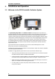
Peristaltic Pump Manual 2 Installation and Operation 2.1 Welcome to the PPS2 Peristaltic Perfusion System The peristaltic pump PPS2 with software control is developed for the perfusion of biological samples. The pumps are driven by stepper motors providing a very long lifetime without maintenance. The durable brushless motors are extremely reliable, show very constant rotation speed, are vibration free and have low electromagnetic emission.
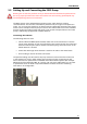
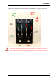
PPS2 Manual 2.2 Setting Up and Connecting the PPS2 Pump Warning: Do not start the perfusion until you have double-checked that the perfusion lines are set up properly and that the inflow and outflow rate are matching. Spilled liquid may irreversibly damage electronic instruments. The PPS2 consists of two independent peristaltic pumps, which both are rotating counterclockwise. The left one is intended for perfusion inlet, the right one for perfusion outlet.
Peristaltic Pump Manual For connecting or changing the tubes, please open the screw and remove the bracket of the pump revolver. Insert the provided tube and fix it with the luer tube connectors in the denoted way. To remount the bracket, take care to insert the bar of the bracket into the corresponding socket on the pump housing. Fix the screw firmly. If you do not need the droplet isolator, please use the circlet and connect the heads of the tube with a luer adapter. 2.2.
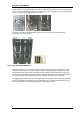
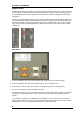
PPS2 Manual Complete Setup The left pump of the PPS2 is intended for perfusion inlet, the right one for perfusion outlet. Please connect all tubing and droplet isolators as indicated on the following image. Take care to use the short Pharmed ® BPT tube between outlet pump and droplet isolator. Warning: The droplet isolators remove pulsation artifacts, but also cause a continuing flow even some time after the pumps are stopped. To avoid flooding, please use hose clamps to stop the flow.
Peristaltic Pump Manual Bubble Detector The bubble detector connected to the outlet detects the amount of bubbles in the outlet tube. A low number of bubbles can indicate that the perfusion outlet cycle is not working properly, so the bubble detector can be used as an alarm system to prevent flooding of the recording equipment. The sensor of the bubble detector is on the left side of the LED, the short Pharmed ® BPT tube has to be guided through the bubble detector as shown on the picture.
PPS2 Manual 2.3 Control Options The PPS2 perfusion system can be controlled via USB connection by the provided software PPS2. In future versions it will be possible to control the PPS2 also with the LTP-Director software from Multi Channel Systems MCS GmbH. The device can also be controlled independently from a computer connection via touch screen. 2.3.1 Operation of the Perfusion Peristaltic Pump with PPS2 Software PPS2 software is running on Microsoft Windows ® systems Windows XP or higher.
Peristaltic Pump Manual Main Window of PPS2 Software Manual Control Mode When using more than one PPS2-System, connected via USB cable, one main window tab page will be available for each PPS2 connected. The tab slider will show the serial number of the deices. The pumps can be operated independently from each other. Only the “Stop” button will affect all connected pumps, all other control functions are independent.
PPS2 Manual Click the button “More” to display further information. At the moment, the default “Analog Range” of the analog input and the internal “Supply Voltage” is noted. For using both pumps independently, deactivate the check box “Fixed Speed Ratio”. With the two sliders, the speed of the left Perfusion (inlet tube) pump, and the right Waste (outlet tube) pump can be controlled.
Peristaltic Pump Manual Stop The “On” and “Off” buttons will affect one pump of the PPS2. The “Stop” button will always stop both pumps. If several pumps are connected with a serial cable, all connected pumps will be stopped. Bubble Detector The bubble detector can be used as an alarm system to prevent flooding of the recording equipment. A light barrier detects the changes of fluid to air in the outlet tube and measures whether this event takes place at least once every ten seconds or not.
PPS2 Manual When looking directly to the rear panel of the PPS2 the pin layout of the digital and analog inputs are as shown on the picture. Connect either a TTL or an analog output device to the respective inputs and select the desired control mode in the PPS2 software. In sum (digital and analog input), the maximum load current for the voltage output (+3.3 V) is 100 mA.
Peristaltic Pump Manual 2.3.2 Operation of the Perfusion Peristaltic Pump via PPS2 Touch Screen Alternatively it is possible to operate the peristaltic pump without software control, via touch screen on top of the device. The touch screen provides the same control functions of the PPS2 which are available via software. The pumps can be operated independently from each other or in a fixed ratio. The “Stop” button will always affect both pumps.
PPS2 Manual The pictures shows the “Main Window” of the touch screen. The “On” and “Off” buttons are connected for the operation of both pumps. The grey color of the upper buttons indicate that no pump is running at the moment, the green color indicates running pumps. Select the check box “Use Bubble Detector” in “Configuration” to switch the bubble detector on and the “Bubbles” indicator will be visible in the “Main window”.
Peristaltic Pump Manual 2.4 Cleaning and Maintenance To clean the peristaltic pump system after use, flush all tubes with distilled water for a few minutes and then quickly with 70 % Ethanol (EtOH). Suck the tubes dry. Disconnect all tube connectors and unscrew the caps of the compound or waste bottle. Empty the bottles and wash them out. Take care not to mistake the tubing when reconnecting. Warning: Make sure no liquid is sucked into the pump revolvers! This can lead to irreversible damage.
PPS2 Manual 3 Application Example: MEA2100-System The peristaltic perfusion PPS2-System consists of two peristaltic pumps. In this application example, one is connected to a reservoir for ringer solution and pumps solution through a perfusion heating PH01 to a MEA recording chamber inside a MEA2100 headstage. The PH01 is connected to a temperature controller TC01/02 and heats the solution to a set value.
Peristaltic Pump Manual 3.2 Perfusion and Noise Low frequency fluctuations in electrophysiological measurements can be caused by the perfusion. Shortly switch off the pump to see whether the fluctuations disappear if the pump is off. 50 Hz noise can also be caused by the perfusion, but is independent of the pump running or not. Perfusion in and out should contain a piece of metal that can be connected to the amplifiers ground to remove 50 Hz noise. The easiest way is to use a bend cannula for suction.
PPS2 Manual 4 Appendix 4.1 Technical Specifications General Information Operating temperature 10 °C to 40 °C Storage temperature 10 °C to 50 °C Dimensions (H x W x D) 235 x 160 x 110 mm Weight 3.6 kg Number of perfusion pump inlets 1 Number of perfusion pump outlets 1 Maximum perfusion rate inlet 30 ml per minute Maximum perfusion rate outlet 30 ml per minute Bubble detector optical fluid flow control Analog and Digital Input Maximal voltage of the digital input + 5.
Peristaltic Pump Manual 4.2 Ordering Information 4.2.1 Scope of Delivery 1 PPS2 main device 1 PPS2 CD (Software and Manual) 1 PPS2 power supply (SPU63-108) 1 power cord, country-specific 1 USB 2.0 cable (A – B) 1 PPRT1.65-10 Fluidic: 3 hose clamps, 2 luer adaptors, 2 circlets Electrical accessories: 1 grounding cable, 1 alligator clip, 2 A/D input connectors Fluidic devices: 2 PPS2-Set-F Optionally 1 MCS Bus cable 4.2.
PPS2 Manual Peristaltic Pump PPS2 Replacement Fluidic Accessories PPS2-Set-FA: Fluidic accessories 3 hose clamps 2 luer adapter 2 circlets Peristaltic Pump PPS2 Replacement Electrical Accessories PPS2-Set-EA: Electrical accessories 1 alligator clip 1 grounding cable 2 D / A input connectors 4.2.
Peristaltic Pump Manual 4.3 Contact Information Local retailer Please see the list of official MCS distributors on the MCS web site. User forum The Multi Channel Systems MCS GmbH User Forum provides the opportunity for you to exchange your experience or thoughts with other users worldwide. Mailing list If you have subscribed to the Mailing List, you will be automatically informed about new software releases, upcoming events, and other news on the product line.