Portable ME-System Manual Portable ME16-System Portable ME32-System
Information in this document is subject to change without notice. No part of this document may be reproduced or transmitted without the express written permission of Multi Channel Systems MCS GmbH. While every precaution has been taken in the preparation of this document, the publisher and the author assume no responsibility for errors or omissions, or for damages resulting from the use of information contained in this document or from the use of programs and source code that may accompany it.
Table of Contents 1 1.1 Introduction About this Manual 1 1 2 2.1 2.2 2.3 Important Safety Advice Important Safety Advice Guarantee and Liability Operator's Obligations 3 3 4 4 3 3.1 3.2 Welcome to the ME-System ME Product Line Portable ME-System 5 5 6 4 4.1 4.2 4.3 4.4 4.5 Software Installation System requirements Recommended BIOS settings MC_Rack Installation Driver Installation Setting up MC_Rack 7 7 7 8 8 9 5 5.1 5.3 The Portable ME-System The Portable ME16-System 5.1.1 Front Panel 5.1.
1 Introduction 1.1 About this Manual It is assumed that you already have a basic understanding of technical and software terms. No special skills are required to read this manual. If you are using the device for the first time, please read the Important Safety Advice before installing the hardware and software, where you will find important information about the installation and first steps. The device and the software are part of an ongoing developmental process.
2 Important Safety Advice 2.1 Important Safety Advice Warning: Make sure to read the following advice prior to installation or use of the device and the software. If you do not fulfill all requirements stated below, this may lead to malfunctions or breakage of connected hardware, or even fatal injuries. Warning: Always obey the rules of local regulations and laws. Only qualified personnel should be allowed to perform laboratory work.
Portable ME-System Manual 2.2 Guarantee and Liability The General conditions of sale and delivery of Multi Channel Systems MCS GmbH always apply. The operator will receive these no later than on conclusion of the contract. Multi Channel Systems MCS GmbH makes no guarantee as to the accuracy of any and all tests and data generated by the use of the device or the software. It is up to the user to use good laboratory practice to establish the validity of his / her findings.
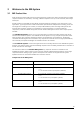
3 Welcome to the ME-System 3.1 ME Product Line With the ME (microelectrode) and STG (stimulus generator) product lines, Multi Channel Systems provides complete solutions for stimulation, recording, and data acquisition from up to 256 channels, data analysis and export. All ME products are intended for extracellular electrophysiological recordings in vivo and special in vitro applications.
Portable ME-System Manual 3.2 Portable ME-System The Portable ME-Systems are compact and lightweight. They feature an integrated 16- or 32-channel filter amplifier and data acquisition. The digitally converted electrode signals are transmitted to the connected computer via USB 2.0 High Speed. The micro preamplifiers are available with 16 or 32 channels. Two miniature preamplifiers MPA8I – OR – one micro preamplifier μPA16 are part of the Portable ME16-System.
Software Installation 4 Software Installation Please check the system requirements before you install the MC_Rack software. Multi Channel Systems MCS GmbH cannot guarantee that the software works properly if these requirements are not fulfilled. Please see the MC_Rack help or manual for more information. It is recommended that you check the MCS web site for software updates on a regular basis. 4.
Portable ME-System Manual 4.3 MC_Rack Installation Download the latest version of MC_Rack form the Multi Channel Systems MCS GmbH web site at http://www.multichannelsystems.com/software/mc-rack. Click the MC_Rack_Setup.exe file and follow the instructions of the installer. It is recommended to use a different hard drive or partition for the operating system and data storage. Please check the web site on a regular basis for free upgrades. 4.
Software Installation 4.5 Setting up MC_Rack Please refer to the MC_Rack manual for more information. Start MC_Rack. Click "Data Source Setup" on the "Edit" menu. In "Channel Layout" dialog select USB-MEA from the left drop down menu and USB-ME from the right drop down menu. Please select 1-dimensional in "Source Layout" and define the number of channels. If you need digital input channel, enable the respective check box. MC_Rack now recognizes the Portable-ME System as data source.
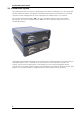
5 The Portable ME-System 5.1 The Portable ME16-System The Portable ME16-System with integrated 16-channel filter amplifier and integrated data acquisition with A / D converter includes two 8-channel miniature preamplifiers (MPA8I) or one 16-channel micro preamplifier (μPA16). The MPA8Is or the μPAs are connected to the microelectrode probes to provide the initial tenfold amplification stage.
Portable ME-System Manual 1 x Analog Input for μPA16. Additionally is on the right side of the front panel of the Portable ME16System one analog input (female D-SUB 26 connector) for a micro preamplifier μPA16 available. Please read the μPA16+μPA32 manual for setting up the μPA16. Note: Only the MPA8I inputs - or - the μPA16 input can be used at a time, as they connect to the same channels on the filter amplifier.
The Portable ME-System The 16 bit digital input channels is a stream of 16-bit values. The state of each bit (0 -15) can be controlled separately, the state can be HIGH (1) or LOW (0). Standard TTL signals are accepted as input signals on the digital inputs. Unused input bits, which have an undefined state, should be masked in the Trigger Detector of MC_Rack.
Portable ME-System Manual 5.2 The Portable ME32-System The Portable ME32-System with integrated 32-channel filter amplifier and integrated data acquisition with A / D converter includes two 16-channel micro preamplifiers (μPA16) or one 32-channel micro preamplifier (μPA32). The μPAs are connected to the microelectrode probes to provide the initial tenfold amplification stage. You can contact standard microelectrodes such as probes from NeuroNexus directly without the need of any adapter in many cases.
The Portable ME-System 1 x Analog Input for μPA32 Additionally is on the right side of the front panel of the Portable ME32-System one analog input (female D-SUB 44 connector) for a micro preamplifier μPA16 available. Please read the μPA16+32 Manual for setting up the μPA16. Note: Only the MPA8I inputs - or - the μPA16 input can be used at a time, as they connect to the same channels on the filter amplifier.
Portable ME-System Manual The 16 bit digital input channels is a stream of 16-bit values. The state of each bit (0 -15) can be controlled separately, the state can be HIGH (1) or LOW (0). Standard TTL signals are accepted as input signals on the digital inputs. Unused input bits, which have an undefined state, should be masked in the Trigger Detector of MC_Rack.
The Portable ME-System 5.3 Setting Up and Connecting the Portable ME-System Warning: Please read the separate manuals of all devices before installation, especially the warnings and safety information. Make sure all devices are switched off before you connect them to the power supply. Damage to the devices and even fatal injuries may result from improper installation or use. 1. Provide a power supply in the immediate vicinity of the installation site. 2.
6 System Components 6.1 Integrated Filter Amplifiers (FA) Raw data from the preamplifiers is amplified by a 16- or 32-channel filter amplifier with fixed gain and bandwidth. A differential amplifier with input type I includes a common ground and a common reference electrode input. The reference electrode is ideally identical to the recording electrodes and placed into a comparable but inactive area or tissue.
Portable ME-System Manual 6.2 Integrated Data Acquisition Analog input signals are acquired from the data source and digitized by the 16- or 32-channel analogdigital converter that is integrated into the main unit. Recorded signals are converted in real-time into digital data streams at sampling rates of up to 50 kHz per channel. You will not miss even the fastest biological signals. Data is transferred to the computer via High Speed USB 2.0 port.
System Components Example: You have a broadband filter amplifier with a bandwidth of 1 Hz to 5 kHz. The expected signals have a maximum frequency of 1 kHz. Therefore, you want to filter the data with a digital low pass filter and a cutoff frequency of 1 kHz.
Portable ME-System Manual Important: It is recommended to set the duration of a TTL pulse according to the sampling rate. The TTL pulse must be long enough to cover at least one data point. For example, if you have a sampling rate of 10 kHz, a data point is recorded each 100 μs. Therefore, TTL input pulses must be at least 100 μs long to make sure that it is detected by the system. MC_Rack will miss some or all pulses if the pulse duration is shorter.
7 Troubleshooting The following hints are provided to solve special problems that have been reported by users. Most problems occur seldom and only under specific circumstances. Please check the mentioned possible causes carefully when you have any trouble with the product. In most cases, it is only a minor problem that can be easily avoided or solved. If the problem persists, please contact your local retailer. The highly qualified staff will be glad to help you.
Portable ME-System Manual 7.2 Triggering / Digital Input does not Work You have connected a TTL source (for example, the Sync Out of a stimulus generator) to the digital input of the Portable ME-System, and configured the virtual rack in MC_Rack for triggering displays or data acquisition by the TTL source, but you do not see any sweeps.
8 Appendix 8.1 Technical Support Please read the chapter "Troubleshooting" of the manual first. Most problems are caused by minor handling errors. Contact your local retailer immediately if the cause of trouble remains unclear. Please understand that information on your hardware and software configuration is necessary to analyze and finally solve the problem you encounter.
Portable ME-System Manual 8.
16-Channel Micro Preamplifier μPA16 The micro preamplifier with 16 electrode inputs μPA16 is connected to the microelectrode probes for providing the initial tenfold amplification stage. Signal integrity is safeguarded and noise pick up is significantly reduced by this preamplifier compared to the use of signal buffers with gain 1. The μPA16 is equipped with an Omnetics socket for NeuroNexus probes C16, C32, F16, and CM16. It has an additional common ground and a reference electrode input.
16-Channel Micro Preamplifier μPA16 Technical Specifications Type μPA16 Operating temperature 0 ° to 50 °C Storage temperature 0 ° to 50 °C Relative humidity 10 % to 85 % non-condensing Dimensions (W x D x H) Length of the cable ca. 17 mm x 17 mm x 2.5 mm w/o connector ca. 21 mm x 17 mm x 2.5 mm with connector 1.5 m Weight ca. 1.
32-Channel Micro Preamplifier μPA32 The micro preamplifier with 32 electrode inputs μPA32 is connected to the microelectrode probes for providing the initial tenfold amplification stage. Signal integrity is safeguarded and noise pick up is significantly reduced by this preamplifier compared to the use of signal buffers with gain 1. The μPA32 is equipped with an Omnetics socket for NeuroNexus probes CM32, F32, HP32, and MRCM32. When using two μPA32 you can connect the NeuroNexus probes H64 and HC64.
32-Channel Micro Preamplifier μPA32 Technical Specifications Type μPA32 Operating temperature 0 ° to 50 °C Storage temperature 0 ° to 50 °C Relative humidity 10 % to 85 % non-condensing Dimensions (W x D x H) Length of the cable Weight ca. 20 mm x 25 mm x 3 mm w/o connector ca. 24 mm x 25 mm x 3 mm with connector 1.5 m ca.
Appendix 8.
Portable ME-System Manual μPA16 Input to Portable ME16-System μPA8I Input (26-Pin D-SUB Connector, female) Pin μPA16 Pin Pin 2 Channel 1 1, 10, 19, 23 GNDP (power ground) Pin 3 Channel 3 20, 21, 22 Positive supply voltage Pin 4 Channel 5 24, 25, 26 Negative supply voltage Pin 5 Channel 7 Pin 6 Channel 9 Pin 7 Channel 11 Pin 8 Channel 13 Pin 9 Channel 15 Pin 11 Channel 2 Pin 12 Channel 4 Pin 13 Channel 6 Pin 14 Channel 8 Pin 15 Channel 10 Pin 16 Channel 12 Pin 17 Ch
Appendix Digital IN / OUT Connector 68-Pin MCS Standard Connector Pin 1 GND Channels bit 0 - 7 Pin 2 GND Pin 3 - 10 Digital output Pin 11 - 14 GND Pin 15 - 22 Digital output Channels bit 8 - 15 Pin 23 - 26 GND Pin 27 - 34 Digital input Channels bit 0 - 7 Pin 35 - 38 GND Pin 39 - 46 Digital input Channels bit 8 - 15 Pin 47 - 48 GND Pin 49 - 63 Not connected Pin 64 - 66 GND Pin 67 Positive supply voltage output Pin 68 Negative voltage supply output D0 OUT Digital Out D0 Bit 0 of
Portable ME-System Manual 8.
Appendix The channel numbers refer to the recording channel numbers in the MC_Rack program. Please make sure that you have selected the Portable ME16-Layout in the MC_Rack program. See the MC_Rack manual or help for details.
Portable ME-System Manual Digital IN / OUT Connector 68-Pin MCS Standard Connector Pin 1 GND Pin 2 GND Pin 3 - 10 Digital output channels bit 0 - 7 Pin 11 - 14 GND Pin 15 - 22 Digital output channels bit 8 - 15 Pin 23 - 26 GND Pin 27 - 34 Digital input channels bit 0 - 7 Pin 35 - 38 GND Pin 39 - 46 Digital input channels bit 8 - 15 Pin 47 - 48 GND Pin 49 - 63 Not connected Pin 64 - 66 GND Pin 67 Positive supply voltage output Pin 68 Negative voltage supply output D0 OUT Digital
Appendix 8.5 Additional Analog Input Portable ME-System with additional ANALOG OUTPUT for amplified analog data via 68-pin MCS standard connector. Rear Panel Analog signals are splitted between the filter amplifier and the A / D converter. The additional analog output on the rear panel of the Portable ME-System has the same pin layout as the output of a FA32 (32-channel filter amplifier). Please see pin layout below.
Portable ME-System Manual 8.6 Contact Information Local retailer Please see the list of official MCS distributors on the MCS web site. User forum The Multi Channel Systems User Forum provides the opportunity for you to exchange your experience or thoughts with other users worldwide. Mailing list If you have subscribed to the General Electrophysiology Mailing List, you will be automatically informed about new software releases, upcoming events, and other news on the product line.
9 Index 35
Portable ME-System Manual A AUDIO 19 C Contact Information 35 D DC Offset Correction 22 DIG IN D 0 19 DIG OUT D 0 19 DIGITAL IN / OUT 19 G GROUND 19 I Integrated Data Acquisition 22 Integrated Filter Amplifiers (FA) 21 M ME Product Line 5 P Pin Layout μPA16 29 Pin Layout μPA32 32 POWER IN 19 Portable ME16-System 11 Portable ME32-System 15 R Remote Control 23 S Sampling Rate 22 Setting up the System 19 Signal Amplification and Filters 21 Software Package 22 System Syn
37