™ nanoZ User Manual
Disclaimer Information in this document is subject to change without notice. No part of this document may be reproduced or transmitted without the express written permission of White Matter LLC. While every precaution has been taken in the preparation of this document, the publisher and the author assume no responsibility for errors or omissions, or for damages resulting from the use of information contained in this document or from the use of programs and source code that may accompany it.
Table of Contents Welcome to the nanoZ ................................................................................................ 1 What’s in the box? ...................................................................................................................................................... 1 Software installation .............................................................................................................................
Adaptor definitions ................................................................................................................................................ 36 Electrode definitions ............................................................................................................................................. 37 Appendix D: NZ-‐CAL Component Values .....................................................................
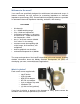
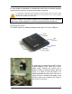
Welcome to the nanoZ Your nanoZ was specifically designed for multichannel microelectrode arrays. It features extremely low test currents for measuring impedance or electrode impedance spectroscopy (EIS). Several inbuilt electroplating modes are provided for automated electrode impedance matching, activation, and cleaning.
nanoZ User Manual Software installation 1. Connect your nanoZ to the computer using the USB cable provided. Let Windows search for the driver on the installation CD (in the Drivers subfolder). Follow the on-screen instructions to install the USB drivers. Note that Windows 7 may have compatible drivers inbuilt, which are fine to use instead. 2. Run 'setup.exe' from the installation CD.
6. If the update is interrupted or cancelled the nanoZ may not function properly. Repeat these instructions to upload the firmware completely. It is advisable to update both the firmware and the software suite to the most recent versions at the same time. Older firmware and device drivers may not work properly with the latest software, and vice versa. The latest software and firmware updates can be obtained from the download page of your vendorʼs website, or from here: http://whitematter.serveftp.net.
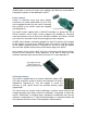
nanoZ User Manual Alternatively, MultiChannel Systems Inc. provides an adaptor (sold separately) with an integrated aluminum rod that can be attached to a micromanipulator. This mounting option is also suitable for in vivo applications. A recalibration is recommended if you intend to use this adaptor (see Appendix E).
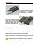
distilled water to remove all traces of the spillage, and allow the circuit board to completely dry before re-assembling the nanoZ. Probe adaptors Probes or electrode arrays that have Samtec connectors (i.e. model number MOLC‐110‐01‐S‐Q) can be plugged directly into the nanoZ, assuming they conform to the nanoZʼs native pin mapping (see Appendix C).
nanoZ User Manual The nanoZʼs electroplating circuit has a native resolution of ~100nA. To enable smaller currents and the ~1nA electroplating accuracy offered by the nanoZ (software v1.4.0 or later), devices shipped prior to April 2012 need to be recalibrated (see Appendix E). The calibration adaptor should be orientated with the ʻNZ-CALʼ text closest to the USB port, and the software should be set to No Adapter / Probe not selected.
Finally, we recommend that the electrode and reference connections are kept as short as possible. Long wires may distort results due to their capacitance. Avoid open ends which act as antennas.
nanoZ User Manual nanoZ Software Overview There are two options for interfacing with the nanoZ: a Windows-based nanoZ application, and the Matlab SDK, which runs under Matlab. Refer to the ʻMatlab software development kitʼ section of the User Manual for detailed instructions on how to control the nanoZ from Matlab. The nanoZ application can be run from the Windows Start menu or Desktop shortcut. The application will connect with the first available nanoZ device.
Clicking on Scope or selecting View | Scope from the main menu will display a virtual oscilloscope with the Z test or plating waveform (output) in green, and the measured (input) waveform in cyan. Use the arrow icons to the right of the scope to change the horizontal (time) and vertical (amplitude) zoom. To switch back to the meter display, click Meter or select View | Meter from the main menu. The status bar displays information about the nanoZ device hardware, including error conditions.
nanoZ User Manual When a channel is active, the corresponding pin on the Adaptor window is highlighted. In passive or impedance testing mode, the pin is highlighted in green; in electroplating mode the pin is highlighted in red. In Manual Control mode (only), left clicking on an adaptor pin will switch the nanoZ to the channel that corresponds to that pin. Channels that have no connection for a given adaptor (as defined in ʻelectrodes.iniʼ) cannot be selected, regardless of operating mode.
mouse button held down, moving the mouse pointer over individual electrode sites will display a small pop-up window with the measured impedance magnitude and phase for that site. Report window When using any of the automated modes of operation, the nanoZ stores impedance and electroplating results in an Excel-like spreadsheet. To view or hide the report window, select View | Report from the main menu.
nanoZ User Manual If the Statistics checkbox is checked, then the average impedance magnitude and phase ± standard deviation of all tested sites is shown at the bottom of each column. Note that if the Condition checkbox is checked, only ʻnormalʼ sites are included in these aggregate statistics. If the Condition checkbox is checked then shorted site impedance values are highlighted in red on the spreadsheet and Probe layout window. Open sites are highlighted in blue. Normal sites are displayed in green.
Operating Modes The nanoZ application has five separate modes of operation for performing a variety of different tasks. These modes can be selected by clicking a button on the left pane of nanoZ application or via the Mode menu on the main menu. The following instructions assume that a suitable electrode adaptor and probe configuration have been chosen, and the electrode sites of interest have been selected in the Probe window. The screenshots below were taken from Windows 7.
nanoZ User Manual Selecting Current (A) mode will apply a DC constant current to the currently selected channel (B) at the level indicated adjacent to the Current level slider (C). The current can be adjusted from -12uA (electrode negative) to +12uA (electrode positive) in ~1nA steps by moving the position of the slider or typing the desired current into the edit box. The voltage across the electrode site will be displayed on the Meter.
Impedance test mode This mode rapidly cycles through all (or a subset) of the channels on the selected probe, measuring the impedance of each electrode. The impedance results are tabulated in the Report window (View | Report). A B C D (A) Set the impedance Test frequency to the desired value. The actual test frequency that will be used is shown in the status bar. (B) Choose the number of Test cycles. The default setting of 40 cycles is a good trade-off between accuracy and speed.
nanoZ User Manual DC electroplate mode This mode cycles through all (or a subset) of the electrodes on the selected probe, applying a controlled DC constant current to each site. It has two submodes of operation: fixed plating time per channel; and match impedances mode, whereby the nanoZ will only advance to the next channel when the electrode site impedance is lowered to the specified Target impedance.
(C) For a fixed plating time per site, set the desired plating Duration. If Test Z is checked, the electrode impedances will be measured before and after plating at the specified test frequency. The Pause setting specifies a delay between electroplating and testing the post-plating impedance, which may be necessary for some plating procedures where the test signal can take several seconds to settle to baseline due to charge buildup on the electrode site.
nanoZ User Manual Impedance spectroscopy mode This mode cycles through all (or a subset) of electrodes on the selected probe, measuring the impedance of each electrode at multiple test frequencies. A B C D (A) Select the impedance Test Frequencies (in Hz) from the check-box list, or check All to test at all frequencies in the list. Click the notepad icon to edit the list of test frequencies. Valid frequencies are between 1Hz and 4986Hz.
impedance spectroscopy results in the Probe report can be saved by clicking the icon or selecting File | Save report from the main menu. Activation mode This mode can be used to increase the charge capacity of all (or a subset of) electrodes on the selected probe.
nanoZ User Manual delay between the activating cycle and testing the post-activation impedance. It may be necessary for some plating procedures where the test signal can take several seconds to settle to baseline due to charge buildup on the electrode site. In most situations this delay can be set to 0~1 second. Use the scope display to check that the impedance test signal is at or close to baseline, and increase the delay if the ʻtest signal clippedʼ warning is reported.
Matlab Software Development Kit The nanoZ Matlab SDK allows users to program customized nanoZ applications that are not supported by the bundled Windows program. To use the Matlab SDK you should have a licensed copy of Matlab installed on the host PC (version 2006a or later) and have the nanoZ SDK installed (refer to the Software Installation section of this User Manual). nanoz MEX library MATLAB applications can access the nanoZ through the ʻnanozʼ MEX files.
nanoZ User Manual getplatingcaps Returns information about the electroplating capabilities preparewaveform Prepares a waveform for use with the startplating function startplating Starts electroplating with an arbitrary waveform startplatingdc Starts DC electroplating with fine control of the current setting getplatingdata Retrieves electroplating voltage feedback data stop Stops impedance metering or electroplating Sample scripts The following demonstration Matlab scripts are provided: ge
Function descriptions getversion Returns the version of the nanoz MEX file. Usage: [major_version, minor_version] = nanoz(‘getversion’); Arguments: none. Return values: major_version, minor_version – major and minor versions of the currently installed nanoz MEX file, respectively. enumdevs Enumerates attached nanoZ devices. Usage: devs = nanoz(‘enumdevs’); Arguments: none. Return value: devs – cell array of strings, one string per each attached device, containing the device-specific serial numbers.
nanoZ User Manual to avoid buffer overrun errors. Making it too large, however, will make the nanoZ less responsive in impedance mode, and limit control of the plating duration. The plating duration resolution is given by dividing the buffer_transfer_size value by the sampling rate (fs_adc). For the recommended value of 64, the minimum plating time/increment is approximately 6ms. close Closes an opened nanoZ device and releases system resources.
selectchannel Selects a channel to perform impedance measurement or electroplating on. Usage: nanoz(‘selectchannel’, handle, channel); Arguments: handle - handle of an opened device returned by the open function; channel – channel number to select, from 1 to 64, or 0 to de-select all channels. Return values: none. Remarks: This function connects the measurement circuit to a specific channel.
nanoZ User Manual Arguments: handle – handle to an opened device returned by the open function; nsam_measure – number of samples to measure per single impedance reading; numdsps – number of overlapping impedance measurements. Return values: none. Remarks: Calling this function initiates the impedance measurement process, applying sinusoidal test current to the target electrode and measuring the voltage across it.
Failure to call this function at regular intervals may result in a buffer overrun error. Recovery from a buffer overrun requires impedance measurement to be stopped. This will cause any pending results to be lost. Note that if a buffer overrun error does occur, the impedance measurement test waveform is still applied to the currently selected channel until the ʻstopʼ function is called. getwaveformcaps Returns information about waveform generation capabilities.
nanoZ User Manual For impedance measurement, the MEX library automatically chooses the best interpolation factor and synthesizes a waveform of appropriate length, to achieve a test signal frequency as close as possible to that specified by the user. For electroplating, arbitrary user-supplied waveforms may be used, which puts the responsibility of choosing waveform length and interpolation factor on the user application. getplatingcaps Returns information about electroplating capabilities.
Return values: raw_waveform – device-specific, raw waveform which is produced on the basis of user-supplied waveform, taking into account device calibration. achieved_current – values of electroplating current, in amperes, which are based on the raw_waveform values returned by this function. Remarks: This function converts the user-specified electroplating currents into raw values that are output by the nanoZ's 8-bit DAC during waveform generation.
nanoZ User Manual If, for whatever reason, the user application crashes during electroplating the nanoZ device will not be informed of it and will continue to supply electroplating current to the target electrode. For this reason it is a good idea to encapsulate electroplating sections of the Matlab code in try/catch clauses, in order to ensure that electroplating is stopped in all cases, even if an error occurs.
reliable way to stop electroplating without generating further errors is to execute a clear nanoz Matlab statement. The m-file examples provided with this SDK implement these safeguards. The nanoZʼs electroplating circuit has a native resolution of ~100nA. To enable smaller currents and ensure the accuracy of the startplatingdc function, devices shipped prior to April 2012 need to be recalibrated (see Appendix E). getplatingdata Retrieves electroplating voltage feedback data.
nanoZ User Manual Consequently, a new impedance measurement on the same channel may start immediately because there will not be any transient channel-switching artifact. The Matlab application should call this function prior to calling any function other than getimpdata or getplatingdata on the target device. Calling other nanoZ library functions may also indirectly stop impedance measurement or electroplating but is not guaranteed to do so.
Appendix A: Principle of Operation For measuring impedance, the nanoZ utilizes a voltage divider circuit: According to Ohm's law, the ratio of voltages V1 and V2 in the circuit is: Rref V1 = 1+ V2 Zx This formula generalizes to AC sinusoidal signals where V1, V2 and Zx are complex numbers whose angles represent phase relations in the circuit.
nanoZ User Manual Appendix B: Technical Specifications Hardware Number of channels 64 Z measurement range 1kΩ to ~100MΩ Z accuracy & precision 1kΩ display resolution ± 1% (10kΩ~15MΩ, 1Hz~2kHz), latest model (see following page) Z test current 1.
The figures below show the measurement error in (A) impedance magnitude and (B) phase as a function of the true impedance magnitude and test frequency, across the working range of the nanoZ. nanoZ model 1.1 (after re-calibration, requires nanoZ software v.1.3.2 or later): A B better than 1% nanoZ model 1.
nanoZ User Manual Appendix C: Channel Mapping The nanoZ application stores adaptor and electrode site mappings in the ʻelectrodes.iniʼ file, which can be accessed from the link in the Windows Start menu. You can use a standard text editor to add, remove, or modify the existing channel mappings, however care must be taken to adhere to the correct syntax described in this Appendix. We recommend you make a backup of ʻelectrodes.iniʼ before making any changes to this file.
the pins in the Adaptor window. If RoundContact is zero, the pins will be square, otherwise they will appear round. 4. the next few lines defines the shape of the adaptor as displayed in the Adaptor window. Typically this will define one or two rectangles representing one or both of the nanoZʼs Samtec connectors, however it can be any shape. The NumPoints field specifies the number of points that comprise the adaptor outline.
nanoZ User Manual dimensions in SiteSizeX and SiteSizeY, thereby allowing for electrode arrays with different site sizes. For simplicity, specify all these values in microns. The ordinal position defines the mapping between the electrode site and the adaptor pin number. So, for example, the 4th line in the MCS 8x8 standard electrode sites definition: Site 45 = -50, 450, means that channel 4 of the adaptor is connected to site 45.
Appendix D: NZ-‐CAL Component Values The following table shows the channel mapping for the bank of test resistors (1% tolerance) and capacitors (5% tolerance) on the supplied NZ-CAL adaptor. channel R (MOhm) C (nF) channel R (MOhm) C (nF) 1 6.8 - 17 short circuit - 2 10 0.1* 18 0.12 - 3 4.7 - 19 1.0 - 4 3.3 - 20 1.0 - 5 20 - 21 0.0051 - 6 2.2 - 22 0.51 - 7 1.0 - 23 0.010 - 8 1.5 - 24 1.0 - 9 10 - 25 - 100 10 1.
nanoZ User Manual Appendix E: Recalibration The nanoZ does not require routine calibrations, however as of April 2012 there are two optional recalibrations available. One will substantially improve the accuracy and range of the impedance testing mode for nanoZ version 1.1 (and may provide a marginal improvement in accuracy for version 1.2).
2 Year Limited Warranty White Matter LLC (White Matter), the manufacturer of the nanoZ, warrants to the original purchaser that the nanoZ will be free from defects in materials and workmanship for two years from the date of purchase. White Matter will repair or replace any nanoZ product or part thereof which, upon inspection by White Matter, is found to be defective in materials or workmanship.