
User guide

8-Channel Miniature Preamplifier Manual
10
7 Pin Layout
7.1 Power Supply
Supply voltage is applied to the output connector pins 8 and 15. The voltage source should supply
a stable noise free voltage. Do not exceed the maximum voltage.
Pin 8: –3 V to –8 V
Pin 15: +3 V to +8 V
Warning: Do not mismatch the polarity of the power supply. A false connection may damage the
unit.
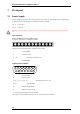
Input Connector
Please note that the black side is considered the top side.
1 Ground (GND)
2 Reference input
3 ... 10 Recording channels 1 to 8
11 Ground (GND)
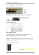
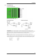
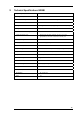
Output Connector (Male)
2
3 4 5 6 7 8
1
9
10 11 12
13
14
15
1 Ground (GND)
9 Signal ground*
2, 10, 3, 11, 4, 12, 5, 13 Recording channels 1 to 8
6, 14, 7 Ground (GND)
15 Positive supply voltage
8 Negative supply voltage
* = Connected to the ground of the amplifier.
The signal ground is used as the reference for the following filter amplifier.