8-Channel Miniature Preamplifier Manual
Information in this document is subject to change without notice. No part of this document may be reproduced or transmitted without the express written permission of Multi Channel Systems MCS GmbH. While every precaution has been taken in the preparation of this document, the publisher and the author assume no responsibility for errors or omissions, or for damages resulting from the use of information contained in this document or from the use of programs and source code that may accompany it.
Table of Contents 1 Important Information and Instruction 1 1.1 Operator's Obligations 1 1.2 Guarantee and Liability 1 1.3 Important Safety Advice 2 2 Welcome to the MPA8I Miniature Preamplifier 3 3 Setting Up and Connecting the MPA 4 3.1 General Setup Recommendations 4 3.2 Testing the Noise Level of the Setup 5 4 Setting up MC_Rack 6 5 Connecting the NeuroNexus Probe 8 6 Service and Maintenance 9 7 Pin Layout 10 7.1 Power Supply 10 7.1.
Important Information and Instruction 1 Important Information and Instruction 1.
-Channel Miniature Preamplifier Manual 1.3 Important Safety Advice Warning: Make sure to read the following advices prior to install or to use the device and the software. If you do not fulfill all requirements stated below, this may lead to malfunctions or breakage of connected hardware, or even fatal injuries. Warning: Obey always the rules of local regulations and laws. Only qualified personnel should be allowed to perform laboratory work.
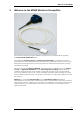
Welcome to the MPA8I 2 Welcome to the MPA8I Miniature Preamplifier The 8-channel miniature preamplifier MPA8I is connected to the microelectrodes for providing the initial tenfold amplification stage. It has additional common ground and reference electrode inputs. The reference electrode is ideally identical to the recording electrodes and placed into a comparable but inactive area or tissue.
8-Channel Miniature Preamplifier Manual 3 Setting Up and Connecting the MPA 3.1 General Setup Recommendations In the following, you find general recommendations for the installation. If you are using NeuroNexus probe adapters available from MCS, please refer to the following chapters for more information. Important: It is important that the complete setup refers to a single common ground. The reference input has always to be connected. It is recommended to use a reference electrode.
Pin Layout If you are not using a Faraday cage, it might be necessary to shield the complete setup with aluminum foil or similar to prevent electrical interference from the outside. Connect the aluminum foil to the ground of the setup, for example, the metal table. Troubleshooting: If you observe problems with noise, check that the ground of the setup is connected to exactly the same ground as the data acquisition computer.
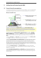
8-Channel Miniature Preamplifier Manual 4 Setting up MC_Rack Please refer to the MC_Rack Manual for more information. Open the file MPA8I_NoiseTest.rck on the installation volume (see folder Tutorial). This rack contains the virtual MC_Card instrument as data acquisition device with a continuous raw data display and an Analyzer to measure the peak-to-peak amplitude. Click Start to start the recording. — OR — Set up the rack on your own: Click Data Source Setup on the Edit menu.
Pin Layout Typical Results Typical results of this test are shown in the following screen shot. The filter amplifier used for this test had a gain of 100 and a bandwidth of 0.5 to 5000 Hz (FA64I-100-0.5-5000). If you use a filter amplifier with a narrower bandwidth, you can generally expect a slightly lower noise level. Noise level test with MPA8I and FA64I-100-0.5-5000 filter amplifier.
8-Channel Miniature Preamplifier Manual 5 Connecting the NeuroNexus Probe Insert one pin array of the NeuroNexus Probe adapter into one MPA8I, and the other into the second MPA8I. Make sure that the orientation of the MPA8I is correct (see illustration). Channel assignment, output pins. Shown are the output pins of the adapter that are connected to the miniature preamplifiers MPAI when looking directly at the pins.
Pin Layout 6 Service and Maintenance Cleaning the Connectors Warning: It is recommended to avoid the use of cleaning solutions to avoid corrosion. If a wet cleaning is required, use distilled water. Make sure that only the connectors touch the liquid; do not submerge the miniature preamplifier or the cable. Otherwise, you can fatally damage the electronics. Clean the connectors with 70 % alcohol and cotton swabs from time to time.
8-Channel Miniature Preamplifier Manual 7 Pin Layout 7.1 Power Supply Supply voltage is applied to the output connector pins 8 and 15. The voltage source should supply a stable noise free voltage. Do not exceed the maximum voltage. Pin 8: –3 V to –8 V Pin 15: +3 V to +8 V Warning: Do not mismatch the polarity of the power supply. A false connection may damage the unit. Input Connector Please note that the black side is considered the top side. 1 Ground (GND) 2 Reference input 3 ...
Pin Layout 7.1.1 Test Model Probe Test signal IN: You can use the jumper to connect the signal input pin (Signal IN) to ground (standard situation for a noise level test), or you can connect a data source, for example, a sine wave generator to the input (and the ground of the test signal to the signal ground input) to test the signal distribution. The input signal is distributed across all recording channels.
8-Channel Miniature Preamplifier Manual 8 Contact Information Local retailer Please see the list of official MCS distributors on the MCS web site. User forum The Multi Channel Systems User Forum provides an excellent opportunity for you to exchange your experience or thoughts with other users worldwide. Mailing list If you have subscribed to the ME-System mailing list, you will be automatically informed about new software releases, upcoming events, and other news on the product line.
9 Technical Specifications MPA8I Operating temperature 0° C to 50° C Storage temperature 0° C to 50° C Relative humidity 10 % to 85 % non-condensing Dimensions (W x D x H) 17 x 25 x 1.8 mm Weight 1.3 g w/o cable and plug, 21 g with cable and plug Length of the cable 1.5 m Maximum tensile strength of cable 20 N Input connector type Single-row precision sockets, 50 mil (1.27 mm) grid pattern, for 0.35 to 0.
8-Channel Miniature Preamplifier Manual 10 Datasheet 14
ADPT-NN-16 16-Electrode NeuroNexus Probe Adapter for MPA8I Amplifiers Connecting two MPA8Is to the adapter ADPT-NN-16 Side view Important: Connect both MPA8Is with the black side down. Otherwise, the preamplifiers do not work. Connect MPA8I No. 1 here Connect MPA8I No. 2 here MPA8I No. 1 MPA8I No.2 Channel assignment, output pins (connected to MPA8I) NeuroNexus Probe NN-ADAPTER MPA8I No. 1 G R 1 2 3 4 5 6 7 8 G MPA8I No.
ADPT-NN-16 16-Electrode NeuroNexus Probe Adapter for MPA8I Amplifiers Connecting the NeuroNexus Probe to the Adapter ADPT-NN-16 Complete setup with NeuroNexus probe and two MPA8Is Important: Black side of MPA8I faced down ! NeuroNexus Probe NN-Adapter MPA8I No. 1 MPA8I No. 2 Top view without probe MPA8I No. 2 1 2 3 4 5 6 7 8 R MPA8I No. 1 8 7 6 5 4 3 2 1 G NeuroNexus Probe-Adapter Channel assignment: Input pins connected to the NeuroNexus probe Pin Layout for MC_Rack: MPA8I No. 1 Pin 1 - 8 No.