32-Channel Miniature Preamplifier Manual
Information in this document is subject to change without notice. No part of this document may be reproduced or transmitted without the express written permission of Multi Channel Systems MCS GmbH. While every precaution has been taken in the preparation of this document, the publisher and the author assume no responsibility for errors or omissions, or for damages resulting from the use of information contained in this document or from the use of programs and source code that may accompany it.
Table of Contents 1 Important Information and Instruction 1 1.1 Operator's Obligations 1 1.2 Guarantee and Liability 1 1.3 Important Safety Advice 2 2 Welcome to the MPA32I 3 3 Setting Up and Connecting the MPA 4 3.1 General Setup Recommendations 4 3.2 Testing the Noise Level of the Setup 5 4 Setting up MC_Rack 6 5 Connecting FlexMEAs 8 5.1 EcoFlexMEAs 10 5.1.1 Connecting 32-Channel NeuroNexus Probes 11 5.1.2 Adapter-NN-32 Pin Layout 12 5.
Important Information and Instruction 1 Important Information and Instruction 1.
32-Channel Miniature Preamplifier Manual 1.3 Important Safety Advice Warning: Make sure to read the following advices prior to install or to use the device and the software. If you do not fulfill all requirements stated below, this may lead to malfunctions or breakage of connected hardware, or even fatal injuries. Warning: Obey always the rules of local regulations and laws. Only qualified personnel should be allowed to perform laboratory work.
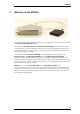
FlexMEAs 2 Welcome to the MPA32I The 32-Channel Miniature Preamplifier MPA32I is connected to the microelectrodes for providing the initial tenfold amplification stage. It has additional common ground and reference electrode inputs. The reference electrode is ideally identical to the recording electrodes and placed into a comparable but inactive area or tissue. Background or noise signals that are picked up by both the reference electrode and the recording electrodes are removed.
32-Channel Miniature Preamplifier Manual 3 Setting Up and Connecting the MPA 3.1 General Setup Recommendations In the following, you find general recommendations for the installation. Important: It is important that the complete setup refers to a single common ground. The reference input has always to be connected. It is recommended to use a reference electrode. However, if you are not using a reference electrode, connect the reference input to ground (GND).
FlexMEAs 6. Connect all unused recording channels to the GND input or to the reference electrode if the reference and ground electrode of the amplifier are short circuited, to avoid noise pickup. As the total amplifier gain generally lies in the range of 1000, even very small noise signals may generate high noise signals. 7. If you are not using a Faraday cage, it might be necessary to shield the complete setup with aluminum foil or similar to prevent electrical interference from the outside.
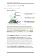
32-Channel Miniature Preamplifier Manual 4 Setting up MC_Rack Please refer to the MC_Rack Manual for more information. Start MC_Rack. Open the file MPA32I_NoiseTest.rck on the installation volume (see folder Tutorial).This rack contains the virtual MC_Card instrument as data acquisition device with a continuous raw data display and an Analyzer to measure the peak-to-peak amplitude. Click Start to start the recording.
FlexMEAs Typical Results Typical results of this test are shown in the following screen shot. The filter amplifier used for this test had a gain of 100 and a bandwidth of 0.5 to 5000 Hz (FA64I-100-0.5-5000). If you use a filter amplifier with a narrower bandwidth, you can generally expect a slightly lower noise level. Noise level test with #MPA8I and FA64I-100-0.5-5000 filter amplifier.
32-Channel Miniature Preamplifier Manual 5 Connecting FlexMEAs FlexMEA36, plastic spacer and adapter (ADPT-FM-32) connected to a 32-channel miniature amplifier MPA32I. The side with no screws is considered the top side of the MPA32I. If the adapter is oriented as shown in the figure, the FlexMEA36 is inserted with the contact pads facing downward. For connecting the FlexMEA72 you need the adapter ADPT-FM-72. Please see the datasheet FlexMEA72 in the Appendix.
FlexMEAs FlexMEAs FlexMEAs are made of flexible polyimide material (Polyimide 2611 foil), perfect for in vivo and special in vitro applications. Only 12 μm "thick" and weighing less than 1 g, the FlexMEA biosensor is very thin and lightweight. FlexMEA36 has 32 titanium nitride (TiN) electrodes plus two internal reference electrodes and two ground electrodes. The flexible base is perforated for a better contact with the surrounding tissue.
32-Channel Miniature Preamplifier Manual 5.1 EcoFlexMEAs EcoFlexMEAs are made of flexible polyimide material (Kapton), perfect for in vivo and special in vitro applications. Only 50 μm "thick" and weighing less than 10 g, the EcoFlexMEA biosensor is thin and lightweight. EcoFlexMEA36 has 32 gold electrodes plus two internal reference electrodes and two ground electrodes. The flexible base is perforated for a better contact with the surrounding tissue.
FlexMEAs 5.1.1 Connecting 32-Channel NeuroNexus Probes Important: REF has to be connected for obtaining a proper signal. Insert the pin array of the NeuroNexus probe into the black connector of the ADPT-NN-32. Connect the MPA32I to the adapter outputs. Make sure that the orientation of the MPA32I is correct (see illustration).
32-Channel Miniature Preamplifier Manual 5.1.2 Adapter-NN-32 Pin Layout The indicated numbers are the ME-System channel numbers that will show up in the MC_Rack program. GND is the ground, REF is the reference input of the miniature preamplifier. Channel Assignment NeuroNexus Probe to MPA32I and MC_Rack The following list shows the assignment to the electrode numbers as given by NeuroNexus Technologies.
FlexMEAs 5.2 Connecting 54-Channel NeuroNexus Probes Important: REF has to be connected for obtaining a proper signal. Connect the two MPA32I to the ADPT-NN-54 adapter outputs. Make sure that the orientation of the amplifiers is correct (see illustration).
32-Channel Miniature Preamplifier Manual ADPT-NN-54 Pin Layout Numbers in italics are the MPA32I pin numbers. The electrode numbers are aligned to the input pins of the MPA32I. The next figure shows the numbering of the polytrode electrodes.
Service and Maintenance 6 Service and Maintenance Cleaning the Connectors Warning: It is recommended to avoid the use of cleaning solutions to avoid corrosion. If a wet cleaning is required, use distilled water. Make sure that only the connectors touch the liquid; do not submerge the miniature preamplifier or the cable. Otherwise, you can fatally damage the electronics. Clean the connectors with 70 % alcohol and cotton swabs from time to time.
32-Channel Miniature Preamplifier Manual 7 Pin Layout 7.1 Power Supply Supply voltage is applied to the output connector pins 19 and 37. The voltage source should supply a stable noise-free voltage. Do not exceed the maximum voltage. Pin 19: –3 V to –8 V Pin 37: +3 V to +8 V Warning: Do not mismatch the polarity of the power supply. A false connection may damage the unit. Input Connector This illustration shows the pin layout viewed from the front, with the case screws upside down.
Pin Layout 7.2 Test Model Probe Test signal IN: You can use the jumper to connect the signal input pin (Signal IN) to ground (standard situation for a noise level test), or you can connect a data source, for example, a sine wave generator to the input (and the ground of the test signal to the signal ground input) to test the signal distribution. The input signal is distributed across all recording channels.
32-Channel Miniature Preamplifier Manual 8 Contact Information Local retailer Please see the list of official MCS distributors on the MCS web site. User forum The Multi Channel Systems User Forum provides an excellent opportunity for you to exchange your experience or thoughts with other users worldwide. Mailing list If you have subscribed to the ME-System mailing list, you will be automatically informed about new software releases, upcoming events, and other news on the product line.
9 Technical Specifications MPA32I Operating temperature 0° C to 50° C Storage temperature 0° C to 50° C Relative humidity 10 % to 85 % non-condensing Dimensions (W x D x H) 27 x 36 x 5 mm Weight 7 g w/o cable and plug, 56 g with cable and plug Length of the cable 1.5 m Maximum tensile strength of cable 20 N Input connector type Dual-row precision sockets, 50 mil (1.27 mm) grid pattern, for 0.35 to 0.
32-Channel Miniature Preamplifier Manual 10 Datasheet 20
FlexMEA36 Flexible Microelectrode Array with 36 electrodes for use with 32-Channel Miniature Preamplifier MPA32I-Flex or with the ADPT-FM-32 adapter and the standard MPA32I. 2200 Dimensions in μm 31000 3000 Temperature compartibility Dimension (W x D) Thickness of the electrode field Weight 10 - 40 °C 31 mm x 18.
FlexMEA36 Electrode Layout 30 m 300 m GND 5 11 22 28 A2 A3 A4 A5 6 12 21 27 29 B1 B2 B3 B4 B5 B6 3 10 13 20 23 30 C1 C2 C3 C4 C5 C6 2 9 16 17 24 31 D1 D2 D3 D4 D5 D6 1 8 15 18 25 32 E1 E2 E3 E4 E5 E6 REF 7 14 19 26 REF F2 F3 F4 F5 300 m GND 4 The numbers in the electrodes are the recording channel numbers that refer to the channel numbers in the data acquisition program.
ADPT-FM-32 FlexMEA36 Adapter for 32-Channel Miniature Preamplifiers MPA32I Connecting the FlexMEA36 via Adapter ADPT-FM-32 to the MPA32I. Plastic Spacer FlexMEA36 MPA32I ADPT-FM-32 MPA32I: The side with no screws is considered the top side of the MPA32I. ADPT-FM-32: If the adapter ADPT-FM-32 is oriented as shown in the figure, the FlexMEA36 must be inserted with the contact pads facing downward. Open the white drawer of the adapter.
FlexMEA72 Flexible Microelectrode Array with 72 electrodes for use via ADPT-FM-72 adapter with two 32-Channel Miniature Preamplifier MPA32I for in vivo and in vitro applications.
FlexMEA72 625 μm 48 17 57 A1 A2 A3 38 27 47 18 56 B1 B2 B3 28 37 46 55 64 C1 C2 C3 36 45 D1 8 17 26 A6 A7 A8 9 18 27 B6 B7 B8 1 10 19 28 C4 C5 C6 C7 C8 54 63 2 11 20 29 D2 D3 D4 D5 D6 D7 D8 35 44 53 62 3 12 21 30 E1 E2 E3 E4 E5 E6 E7 E8 34 43 52 58 7 13 22 31 F1 F2 F3 F4 F5 F6 F7 F8 33 42 49 59 6 16 23 32 G1 G2 G3 G4 G5 G6 G7 G8 REF 40 50 60 5 15 25 REF H2 H3 H4 H5 H6 H7 41 51 61 4 14 2
ADPT-FM-72 FlexMEA adapter for connecting two MPA32Is to the FlexMEA72 Connector for FlexMEA72 GND Connector ADPT-FM-72 Connector for FlexMEA72 Connector for MPA32I No. 2 Connectors for FlexMEA72 Connector for MPA32I No. 1 Plastic Spacer Adapter ADPT-FM-72 connected to both MPA32Is. FlexMEA72 ADPT-FM-72: The adapter is equipped with the connectors for the MPA32Is on one side and the connectors for the FlexMEA72 on the other side.
ADPT-FM-72 FlexMEA adapter for connecting two MPA32Is to the FlexMEA72 Please follow the instructions for mounting the the FlexMEA72 on the ADPT-FM-72 and the MPA32Is step by step. Necessary tools: A small Philipps head screwdriver a sharp forceps 1. Please loosen the screws of the adapter that it is possible to move the bars of the ADPT-FM-72. 2. Open the withe drawers of the adapter by pre-drawing the black parts of the drawers with the help of a forceps. 3.
ADPT-NN-32 32-Electrode NeuroNexus Probe Adapter for MPA32I Amplifiers Connecting the NeuroNexus probe and the MPA32I Warning: The adapter may only be used together with the MPA32I from Multi Channel Systems MCS GmbH and the 32-channel probe from NeuroNexus, and only for the specified purpose. Damage of the device and even fatal injuries can result from improper use. ! The side with no screws is considered the top side of the MPA32I.
ADPT-NN-32 32-Electrode NeuroNexus Probe Adapter for MPA32I Amplifiers Pin layout of the input connector Pin assignment The indicated numbers are the ME-System channel numbers that will show up in the MC_Rack program. The list on the second page shows you the assignment to the electrode numbers as given by NeuroNexus Technologies. GND is the ground, REF is the reference input of the miniature preamplifier. Please see the MPA32I manual for details.
ADPT-NN-54 54-Electrode NeuroNexus Probe Adapter for MPA32I Amplifiers Connecting two MPA32I to the ADPT-NN-54 Complete setup with two MPA32Is IN/OUT 1 IN/OUT 2 Top view MPA32I No. 1 MPA32I No. 2 The IN / OUT sockets 1 and 2 can be used as output connectors, for connecting single channels to other devices, or as input connectors, for connecting other signal sources. Side view Connect MPA32I No. 1 here Top Bottom Connect MPA32I No.
ADPT-NN-54 54-Electrode NeuroNexus Probe Adapter for MPA32I Amplifiers Pin Layout Adapter to 54-electrode NeuroNexus probe MPA32I No. 1, IN / OUT 1 1 3 5 GND REF 2 4 7 9 11 13 15 17 19 21 23 25 27 29 31 12 10 8 6 4 2 27 25 23 15 17 19 21 33 35 REF 13 11 9 7 5 3 1 26 24 14 16 18 20 22 6 8 10 12 14 16 18 20 22 24 26 28 30 32 34 GND 33 36 MPA32I No.
ADPT-NN-64 Adapter for connecting two MPA32Is to the Acute 64 Probe from NeuroNexus Technology ADPT-NN-64 ADPT-NN-64 MPA32I No. 1 MPA32I No. 2 Acute 64 Probe Electrodes Acute 64 Probe Schematic diagram : Connect the male pins at the bottom side of the Acute 64 Probe to the female pins at the bottom side of the adapter ADPT-NN-64. Connect the upper output pins at the top side of the adapter ADPT-NN-64 to the MPA32I No. 1. It is mandatory, that the top side of the MPA32I No. 1 faces upwards.
ADPT-NN-64 Adapter for Acute 64 Probe from NeuroNexus Technology Acute 64 Probe Site Mapping (Electrode Layout) Pin Layout : MC_Rack MPA32I No. 1 and No.