2-Channel Miniature Preamplifier Manual
Information in this document is subject to change without notice. No part of this document may be reproduced or transmitted without the express written permission of Multi Channel Systems MCS GmbH. While every precaution has been taken in the preparation of this document, the publisher and the author assume no responsibility for errors or omissions, or for damages resulting from the use of information contained in this document or from the use of programs and source code that may accompany it.
Table of Contents 1 Important Information and Instruction 1 1.1 Operator's Obligations 1 1.2 Guarantee and Liability 1 1.3 Important Safety Advice 2 2 Welcome to the MPA2I Miniature Preamplifier 3 3 Setting Up and Connecting the MPA 4 3.1 General Setup Recommendations 4 4 Service and Maintenance 5 5 Pin Layout 6 5.1 Power Supply 6 5.2 Input Connector 6 5.
Important Information and Instruction 1 Important Information and Instruction 1.
2-Channel Miniature Preamplifier Manual 1.3 Important Safety Advice Warning: Make sure to read the following advices prior to install or to use the device and the software. If you do not fulfill all requirements stated below, this may lead to malfunctions or breakage of connected hardware, or even fatal injuries. Warning: Obey always the rules of local regulations and laws. Only qualified personnel should be allowed to perform laboratory work.
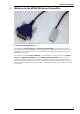
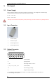
Welcome to the MPA2I 2 Welcome to the MPA2I Miniature Preamplifier The 2-Channel Miniature Preamplifier MPA2I is connected to the microelectrodes for providing the initial tenfold amplification stage. It has additional common ground and reference electrode inputs. The reference electrode is ideally identical to the recording electrodes and placed into a comparable but inactive area or tissue.
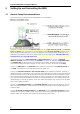
2-Channel Miniature Preamplifier Manual 3 Setting Up and Connecting the MPA 3.1 General Setup Recommendations In the following, you find general recommendations for the installation. Important: It is important that the complete setup refers to a single common ground. The reference input has always to be connected. It is recommended to use a reference electrode. However, if you are not using a reference electrode, connect the reference input to ground (GND).
If you are not using a Faraday cage, it might be necessary to shield the complete setup with aluminum foil or similar to prevent electrical interference from the outside. Connect the aluminum foil to the ground of the setup (for example, the metal table). Troubleshooting: If you observe problems with noise, check that the ground of the setup is connected to exactly the same ground as the data acquisition computer.
2-Channel Miniature Preamplifier Manual 5 Pin Layout 5.1 Power Supply Supply voltage is applied to the output connector pins 8 and 15. The voltage source should supply a stable noise-free voltage. Do not exceed the maximum voltage. Pin 8: –3 V to –8 V Pin 15: +3 V to +8 V Warning: Do not mismatch the polarity of the power supply. A false connection may damage the unit. 5.2 5.
Contact Information 6 Contact Information Local retailer Please see the list of official MCS distributors on the MCS web site. User forum The Multi Channel Systems User Forum provides an excellent opportunity for you to exchange your experience or thoughts with other users worldwide. Mailing list If you have subscribed to the mailing list, you will be automatically informed about new software releases, upcoming events, and other news on the product line.
2-Channel Miniature Preamplifier Manual 7 Technical Specifications MPA8I Operating temperature 0° C to 50° C Storage temperature 0° C to 50° C Relative humidity 10 % to 85 % non-condensing Dimensions (W x D x H) 12 x 31 x 3 mm Weight 1.3 g w/o cable and plug, 21 g with cable and plug Length of the cable 1.5 m Maximum tensile strength of cable 20 N Input connector type Single-row precision sockets, 50 mil (1.27 mm) grid pattern, for 0.35 to 0.