
System Manual User Manual

MEA2100-System Manual
56
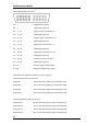
MEA2100 Interface Board: Digital IN / OUT Connector
68-Pin MCS Standard Connector
Pin
1 GNDP (power ground)
Pin
2 GNDS (signal ground)
Pin
3
-
10 Digital output channels bit 0
-
7
Pin
11
-
14 GNDS (signal ground)
Pin
15
-
22 Digital output channels bit 8
-
15
Pin
23
-
26 GNDS (signal ground)
Pin
27
-
34 Digital input channels bit 0
-
7
Pin
35
-
38 GNDS (signal ground)
Pin
39
-
46 Digital input channels bit 8
-
15
Pin
47
-
48 GNDS (signal ground)
Pin
49
-
63 Internal use (do not connect)
Pin
64
-
66 GNDS (signal ground)
Pin
67 Positive supply voltage output
Pin
68 Negative voltage supply output
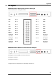
Digital IN / OUT, separate available via Lemo Connectors
Separate Digital IN Lemo Connectors
Digital In 1 Bit 0 of the 16 bit digital input channels (Pin 27)
Digital IN 2 Bit 1 of the 16 bit digital input channels (Pin 28)
Digital IN 3 Bit 2 of the 16 bit digital input channels (Pin 29)
Digital IN 4 Bit 3 of the 16 bit digital input channels (Pin 30)
Separate Digital OUT Lemo Connectors
Digital
OUT 1 Bit 0 of the 16 bit digital output channels (Pin 3)
Digital OUT 2 Bit 1 of the 16 bit digital output channels (Pin 4)
Digital OUT 3 Bit 2 of the 16 bit digital output channels (Pin 5)
Digital OUT 4 Bit 3 of the 16 bit digital output channels (Pin
6)