
System Manual User Manual

Software
19
Use of the Digital Channel in the MEA2100-System
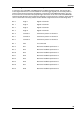
In contrast to the other MEA- and ME-Systems from Multi Channel Systems, the 16 input bits
of the digital channel are not all accessible for external trigger signals, but are mostly used for
internal communication between the different components of the MEA2100-System. Only the
first four bits are connected to the physical DigIn connectors on the front side of the MEA2100
interface board. Most bits are permanently assigned to certain functions. However, these settings
can be customized if necessary. Please see the channels assignments from the following table.
Bit
0 DigIn 1 Digital In channel 1
Bit
1 DigIn 2 Digital In channel 1
Bit
2 DigIn 3 Digital In channel 1
Bit
3 DigIn 4 Digital In channel 1
Bit
4 Stimulus 1 Stimulation pattern on channel 1
Bit
5 Stimulus 2 Stimulation pattern on channel 2
Bit
6 Stimulus 3 Stimulation pattern on channel 3
Bit
7 Zero not connected
Bit
8 RF 1 Real-time feedback specification 1
Bit
9 RF 2 Real-time feedback specification 2
Bit 10 RF 3 Real-time feedback specification 3
Bit 11 RF 4 Real-time feedback specification 4
Bit 12 RF 5 Real-time feedback specification 5
Bit 13 RF 6 Real-time feedback specification 6
Bit 14 RF 7 Real-time feedback specification 7
Bit 15 RF 8 Real-time feedback specification 8